Catalog excerpts

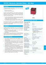
Electronic Standard Relay - ISO Maxi Description The electronic standard relay ESR10 is a solid state power relay combining two functions in a single unit. ● ● solid state relay function electronic overcurrent protection The relay has been designed for 4-pole standard automotive relay sockets to ISO 7588. It is suitable for DC12V on-board electrical systems and is rated 50A. Up to now two separate components were connected to one functional unit in a load circuit to allow remote switching and protection of loads: an electro-mechanical relay or solid state relay which is powered via the control cable and then closes the circuit by means of the integral contact or power semi-conductor. ● an additional protective element (circuit breaker or fuse) providing line or equipment protection in the event of a failure. ● By combining two functions in one component the ESR10 helps to minimise the number of plug-in connections in a circuit and thus reduces the risk of a failure. In addition the ESR10 is remotely resettable after overload tripping. ESR10 Technical data (Tamb = 25 °C, UN) Voltage supply LINE+ Current rating IN The ESR is suitable for all applications in DC 12 V on-board electrical systems where magnetic valves, motors or lamps have to be switched and protected: ● Road vehicles (work vehicles, emergency cars, buses, special vehicles, trucks, passenger cars, bikes) ● Construction vehicles and agricultural vehicles ● Rail vehicles Of course the ESR10 is also suitable for the use in industrial applications (process control and production technology) as well as in the marine sector (work boats, sport-, motor- and sailing boats, yachts etc.) Closed current I0 in OFF condition1): Load circuit LOAD Load output Load types Protective function Current rating IN Voltage drop1) UON Trip current 1)2) The exclusively solid-state based power electronics of the ESR10 offer wear-free switching function, unsusceptible to shock, vibration and dust. Compared to electro-mechanical relays, it requires only a fraction of the closed current and switching current. This is of the essence for battery-buffered load circuits which have to stay actuated even with the generator in the OFF condition and it helps to reduce the CO2 emissions. In the event of a short circuit (ESR10-N) or of a short circuit plus overload (ESR10-P) the load circuit is disconnected. After trip on grounds of short circuit or overload and upon remedy of the failure, the ESR10 can easily be reset by simply switching it off and on, i.e. the ESR10-P works as a resettable fuse. There is no automatic re-start. Reset can alternatively be effected by resetting the supply voltage. For switching and monitoring loads of 50 A plus, it is possible to connect several devices in parallel. Equal distribution of current onto the individual units has to be ensured by a symmetrical design of the cables (length and cross section). Trip time2) Max. overload Free-wheeling diode for connected load Control input IN+ Control voltage IN+ Power MOSFET plus switching (HSS) resistive, inductive and capacitive N short circuit proof, temperature shutdown P additional overload disconnection after ttrip at I ≥ Itrip 50 A 60 mV (at IN) Itrip 1.3 x IN ttrip 200 ms (at overload) 400 A (at L/R = 2-3 ms) integral Control current IN+ Switching frequency at resistive or inductive load Rising edge of IN+ < 5 ms Control input INControl voltage INrelay is ON when IN connected to ground 0...5 V = ON, 8.5...16 V = OFF Control current IN+ 1.5 mA at 0 V Switching frequency at resistive max. 60 Hz or inductive load Rising edge of IN< 5 ms 1) 2) typical P-type only
Open the catalog to page 1
Electronic Standard Relay - ISO Maxi Technical data (Tamb = 25 °C, UN) General Characteristics Reverse polarity protection control circuit load circuit Delay times Temperature range Temperature shutdown Housing Protection class Material Dimensions plugged in including terminals Mass1) 1) Approvals Approval authority yes no (due to integral free-wheeling diode) tON / tOFF .5 ms / 1.5 ms 0 -40 °C…85 °C power transistor > 150°C IP54 cover PA66-GF30 base plate PA6-GF30 ISO standard Maxi 30 x 30 x30 mm 30 x 39 x 41.6 (44.3) mm 55 g control input load output Order numbering code Humid heat...
Open the catalog to page 2
Electronic Standard Relay - ISO Maxi Time/current characteristic (Tamb = 25 °C) Schematic diagram Option „HP“ (control input IN+) trip time in seconds 1 2 typically 1.3 x I N times rated current IN Option „HN“ (control output IN-) 2 and 8 - blade terminals 9,5 x 1,2 4 and 6 - blade terminals 6,3 x 0,8 All dimensions without tolerances are for reference only. In the interest of improved design, performance and cost effectiveness, the right to make changes in these specifications without notice is reserved. Product markings may not be exactly as the ordering codes. Errors and omissions...
Open the catalog to page 3All E-T-A Elektrotechnische Apparate catalogs and brochures
-
High Power-D-Box®
4 Pages
-
Economy Power-D-Box®
4 Pages
-
PBM-1170-05-V0060
2 Pages
-
PBM-E1048-8..-B.-V0089
3 Pages
-
PowerPlex® Power Module
6 Pages
-
PowerPlex® Panel Module
6 Pages
-
PowerPlex® Compact Module
6 Pages
-
MPR10
4 Pages
-
SVS14
6 Pages
-
SVS15
8 Pages
-
SVS16
6 Pages
-
SVS18
6 Pages
-
SVS20
8 Pages
-
PP-M-PM024
6 Pages
-
PP-M-DC024
6 Pages
-
E-1048-8D...
4 Pages
-
3131-A
6 Pages
-
1620
2 Pages
-
PowerPlex® Touch Panel 4.3?
2 Pages
-
D_8340-G2
5 Pages
-
D_1120
3 Pages
-
D_1110
2 Pages
-
E-1048-8D
3 Pages
-
E-1048-8I
5 Pages
-
E-1048-8C.
4 Pages
-
8340-F
6 Pages
-
8340-G2
5 Pages
-
1610-21
3 Pages
-
1110
2 Pages


