
- Catalogs
- Dickinson Marine
- BEAUFORT-00-BEA.PDF

BEAUFORT-00-BEA.PDF

BEAUFORT-00-BEA.PDF
Ensure all installation and operating procedures are followed. Proper installation of the flue and a fresh air inlet vent near the stove is crucial for safe operation. Fuel supply must have manual shut-offs and be filtered to at least 10 microns, not exceeding 4 PSI. Only specified components should be used, and the stove should not be left unattended.
Location: The stove should be installed with safety clearances and heat retardant materials. The flue stack should be straight and properly sized.
Mounting and Securing: Secure the stove with the provided tie-down bar and ensure it is level.
The flue stack must be straight and correctly sized, with a barometric damper installed between 12” and 24” from the stove exhaust collar to maintain optimal combustion.
Fuel should be supplied from a gravity feed tank or low-pressure pump, with a regulator if pressure exceeds 4 PSI. Use a 3/8" flare fitting for the fuel inlet.
Use 12 volt DC pumps with specific lift capacities, install a fuel oil filter before the pump, and ensure the pump is in a ventilated area.
Use a low-pressure fuel delivery pump and install a check valve to prevent backflow. Regular maintenance of the fuel filter and shut-off valve is necessary.
The valve is calibrated for #2 diesel, and adjustments may be needed for different fuels. Ensure the overflow fitting is not plugged.
Adjust the flow if the stove is burning rich or lean, using the valve knob and metering screw for precise adjustments.
Follow detailed steps for valve maintenance, including safety features like a high-temperature fuse.
Ensure correct placement of burner components and good ventilation for proper combustion.
Install a CO alarm and manage draft to prevent inefficient burning.
The fan boosts draft during start-up and in windy conditions but requires adjustments to avoid running too lean.
Ensure proper spacing, insulation, and configurations for exhaust pipes and fuel lines.
Engage the fuel supply, ignite with a tissue, and use the fan to maintain the flame.
Adjust air supply with fuel metering valve adjustments to maintain a proper mixture.
Turn off and monitor a flooded burner until excess fuel is burned off.
Specifications for installing a hot water heating coil are provided.
Regular cleaning is necessary to remove carbon build-up.
Instructions for replacing the burner include proper sealing of the combustion chamber.
Address blockages by cleaning the fuel line and checking for leaks.
Regular maintenance includes cleaning fuel lines, combustion chamber, and cooktop.
Preheat the stove for cooking and use the oven damper for heat control.
Guidance is provided for common issues like no fuel in the burner and carbon build-up.
Information on using bio-diesel and converting to other fuels is available.
One-year warranty covers defects, with exclusions for normal wear and misuse. Registration is required within 30 days of purchase.
Catalog excerpts

Dickinson Marine #407-204 Cayer St Coquitlam BC Canada V3K 5B1 www.dickinsonmarine.com [email protected] T: 800 659 9768 SINCE 1932 Atlantic/Beaufort Diesel Cookstove Operator’s Manual This manual must be read and the requirements carried out to ensure satisfactory performance. DICKINSON RESERVES THE RIGHT TO MAKE CHANGES TO PRODUCTS OR DOCUMENTS AT ANY TIME QUALITY INSPECTED BY- Doug & Don DATE- Nov 5/2008
Open the catalog to page 1
-1- CONTENTS Warnings and Disclosures pg-2 Burner Assembly pg-17 Installation Diagram pg-3 Burner Diagram pg-18 Clearance Diagram pg-4 Combustion Air pg-18 Location pg-4 Draft Assist Fan pg-19 Mounting and Securing pg-5 Checklist pg-20 Flue Stack (chimney) pg-6 Lighting Instructions pg-21 Barometric Install pg-6 Operating tips pg-23 Fuel Supply pg-7 Flooding Burner pg-24 Fuel Pump Install pg-8 Water Coil Option pg-24 Fuel Overflow pg-9 Coil Install pg-25 Fuel Diagram pg-10 Burner Cleaning pg-26 Fuel Variations pg-11 Burner Replacement pg-27 Fuel Measurement &Adjustment pg-12 Re-Cementing pg-29...
Open the catalog to page 2
-2- Warnings and Disclosures - Follow all installation and operating procedures. - The oil stove requires an installed flue for correct operation. Do not attempt to operate the stove without the flue chimney installed correctly as required in this manual. - A permanently open fresh air inlet vent must be installed near the stove to provide air to the stove for combustion. - The fuel supply must have a manual shut-off at the fuel tank as well as a manual shut-off near the stove. - The fuel must be filtered to at least 10 microns and not exceed 4 PSI of pressure. - The fuel type stamped on the...
Open the catalog to page 3
-3- Installation Diagram NOTE: Not all installations will require a pump, gravity tank, elbows, or coil options
Open the catalog to page 4
-4- Clearance Diagram Installation Guidelines Location The location of the stove must be large enough to provide safety clearances. Objects and materials closer to the stove than 6” must be lined with high density, heat retardant insulation and covered with metal (stainless steel, aluminum, etc.). Another alternative is using ceramic tiles. Particular care must be taken to protect the surfaces close to the cast iron top and first section of flue pipe. The install location should also take into account the length and configuration of the flue stack. It is generally preferable that the flue stack...
Open the catalog to page 5
-5Ideally, the stove should face the bow or stern of your vessel, particularly on a sailboat. Fuel gravity feeds from the oil-metering valve into the burner. Should this valve drop below the level of the burner fuel will not flow uphill into the burner and the fire will go out. In a beam-facing sailboat installation, the oil metering valve may have to be relocated to the side of the stove. There are holes in the side panel to hold the repositioned valve bracket. If you have any doubt regarding the need for a valve bracket, please ask your dealer or email [email protected] Mounting and...
Open the catalog to page 6
-6- Flue Stack The length and straightness of the flue stack are important to the efficient operation of the stove. The Flue stack must be the correct diameter. If elbows must be used, the elbows shall not be greater than a 45 degree angle. The first elbow should not be closer than 12” (28cm) to the stove. Allow for as much straight pipe as possible before the first elbow. The pipe will attach to the stove by squeezing the round pipe over the oval flue collar when installing. Pipe Diameter 5 inch dia. 12.7cm Recommended Length 6 ft 1.83m Minimum Length 4 ft 1.23m Hole Diameter 7 inch dia. 17.8cm...
Open the catalog to page 7
-7The draft above the top of the fire will be aprox -.05 inches of water column, should you have a draft meter, however adjusting the damper as above should get you close enough. Dickinson can supply you with a stainless steel thru-deck fitting for your pipe installation. The thru-deck fitting includes a stainless steel dress ring for the interior of the cabin and a rubber (neoprene) gasket easy mounting. Depending on the contour or the angle of the cabin top, you may need to make a hardwood spacer block. One surface of the block would be a level plane to mate to the deck cap. The other would...
Open the catalog to page 8
-8#20-000 FRD-2 3 PSI FUEL PUMP & #20-002 FRD-HD c/w REGULATOR FUEL PUMP • • • • • • • • • • These are 12 volt DC pumps. The factory spring pressure for the #20-000 FRD-2 pump is set at 3 PSI (max 6 ft. lift). The #20-002 FRD-HD pump has a stronger pressure spring that will draw the fuel higher (max 15 ft. lift) but will need the regulator to adjust the pressure down to 3 PSI before the fuel goes to the oil metering valve. You must use a fuel oil filter in your installation before the pump to keep debri from plugging up the 3 check valves inside the pump. When the oil metering valve (carburetor)...
Open the catalog to page 9
-8Ainstalled as per diagram. Place the check valve as shown in the diagram on top of the heavier replacement spring, and the spring on top of the pump plunger and push it back into the pump body holding it in with a finger. Note the magnetic part of the plunger is on the opposite end of the spring. Replace the lid with the gasket on by lowering your finger on to the red O ring sleeve without the plunger falling out ( the plunger is about 2” long so you have room to lower your finger out of the way). The red O ring sleeve will fit inside the pump tube and the black O ring will fit over the outside...
Open the catalog to page 10
-8B- #20-002 FRD-HD c/w REGULATOR We recommend using an elbow fitting on the fuel inlet. When priming this pump hold down the knob of the pressure regulator to prime the fuel lines and take out the air then turn the dial to the lowest setting on the regulator and increase pressure 1 increment at a time until the pump is just delivering a small amount of fuel as the heater/stove only requires a very small amount .
Open the catalog to page 11
-9Use 3/8" (9.52 mm) copper fuel line for the first 2-3 ft closest to the heater/stove. Approved hose can be used for the remainder of the installation. DO NOT USE A PRESSURIZED FUEL TANK. When a low pressure fuel delivery pump is used (less than 4 psi) a fuel line must be plumbed directly from the main fuel tank or tee in at the tank (not from the engine supply line or engine filter). Use a check valve in the stove fuel line to stop the engine from pulling back the fuel and starving the stove. The fuel inlet is a 3/8" flare fitting. To keep the oil metering valve clean and trouble free install...
Open the catalog to page 12All Dickinson Marine catalogs and brochures
 Mediterranean / Caribbean
26 Pages
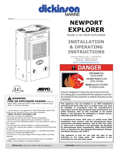 Explorer Propane Fireplace
54 Pages
 Propane Heater P9P12
31 Pages
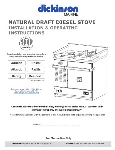 Diesel Stove
53 Pages
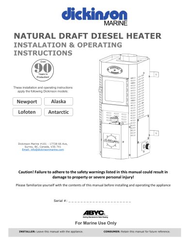 Diesel Heater
53 Pages
Archived catalogs
 LOFOTEN-00-LOF - Pdf
41 Pages
 Lofoten Diesel Heater
1 Page
 NEWPORT P9000-P12000
1 Page
 ANTARCTIC DIESEL HEATER
1 Page
 Alaska-00-ALA Pdf
41 Pages
 Pacific-00-PAC . PDF
39 Pages
 BRISTOL-00-BRI.PDF
38 Pages
 BERING-00-BER . PDF
38 Pages
 Small SEA-B-QUE
1 Page
 Large SEA-B-QUE
1 Page
 Round SEA-B-QUE
1 Page
 Spitfire 180
1 Page
 Propane 2 Burner Cooker
1 Page
 Alaska Diesel Heater
1 Page
 Antarctic Diesel Heater
1 Page
 Newport Diesel Heater
1 Page
 Diesel Cook-Stoves
2 Pages
 Dickinson Cabin Heaters
2 Pages
 Dickinson Marine BBQ
1 Page


