
- Catalogs
- Dessalator
- SOLO 100

- Products
- Catalogs
- News & Trends
- Exhibitions
SOLO 100
SOLO 100
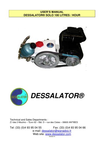
The Dessalator® SOLO 100 comprises a hull valve, pre-filter, motor-pump unit, membrane unit, control panel, and necessary pipes and hoses. Additional assembly hardware includes screws, clips, and tools.
- Sea Water Inlet: Position the strainer below the waterline, seal with mastic, and ensure accessibility for maintenance.
- Motor Unit: Install horizontally, low in the boat, and protect from water spray. Ensure proper air circulation for cooling.
- Membrane Unit: Install vertically or horizontally. Use insulating tubes for hoses to reduce vibration.
- Control Panel: Mount vertically near the motor/pump unit and membranes, ensuring space for connections.
Ensure valves are open, rinse if unused for days, start with pressure regulator open, adjust pressure, and monitor water quality. Shut down by reducing pressure and activating the rinsing valve.
Membranes require careful maintenance. Avoid extreme temperatures and ensure membranes remain immersed in liquid. Use in clean sea water to prevent clogging and damage.
- Cleaning Membranes: Clean after 800 hours or if water production drops by 10-15%. Use a cleaning solution and rinse thoroughly.
- General Maintenance: Regularly check and maintain all components for optimal performance.
Spare Parts: Includes filters, driving belts, motor relays, solenoid valves, HP pump seals, hoses, connectors, and flowmeter tubes.
Accessories: Sterilizing cartridge ST2, sterilizer bag, and mineralizing cartridge.
Principle: Sea water is forced through membranes at high pressure, allowing only pure water to pass. The system rejects 99% of TDS, ensuring drinking water with a TDS value of 500. Fresh water storage should be treated with chlorine or iodine and mineralized.
Operation: Sea water is filtered and pressurized, with fresh water directed to the tank if salinity is acceptable. Production capacity decreases with lower sea water temperatures.
Instructions include screwing the brass union onto the HP pipe, inserting and tightening the steel end-piece, and ensuring the connector does not block the hose.
Steps include closing the sea water inlet valve, preparing the sterilizing cartridge, and rinsing the system with fresh water. The sterilization is effective for six months.
Details the valve positions for manual rinsing and sterilization versus normal operation.
Provides solutions for common issues such as leaks, pressure problems, noisy pumps, and insufficient water flow. Solutions include tightening components, cleaning or replacing parts, and ensuring proper power supply.
Catalog excerpts
USER’S MANUAL DESSALATOR® SOLO 100 LITRES / HOUR DESSALATOR® Technical and Sales Departments : Z.I des 3 Moulins – “Euro 92 – Bât. D – rue des Cistes – 06600 ANTIBES Tel: (33) (0)4 93 95 04 55 Fax: (33) (0)4 93 95 04 66 e-mail: [email protected] Web site: www.dessalator.com Version A
Open the catalog to page 1
CONTENTS 1. Components page 1 2. How to install the desalinator: Sea water inlet page 2 Motor unit page 3 Membrane unit page 4 Control panel page 5 3. Starting the Dessalator® page 6 4. Directions for use (membranes) page 7 5. Maintenance: Cleaning the membranes page 8 Sterilizing the membranes page 9 High pressure pump page 9 6. Spare parts and accessories page 10 Appendix: A1: Reverse osmosis page 11 A2: How to assemble the HP connectors page 12 A3: Sterilizing cartridge – Instructions for use page 13 A4: Automatic rinsing page 14 A5: Troubleshooting page 15 Connection plan DES 12/24/230V April...
Open the catalog to page 2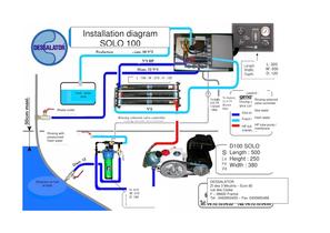
Installation diagram SOLO 100 L: 320 W: 200 D: 120 L : 700 ; W : 270 ; H : 120 fresh water tank Legend : To battery 2x 0.75 Brown blue Waste outlet Rinsing solenoid valve controller Rinsing solenoid valve controller Sea water fresh water HP tube pump / membrane Rinsing with pressurized fresh water D100 SOLO Length : 500 Height : 250 Width : 380 Strainers on hull of boat H: 410 W: 310 D: 180 DESSALATOR ZI des 3 Moulins – Euro 92 rue des Cistes F – 06600 France Tel : 0493950455 – Fax :0493950466
Open the catalog to page 3
A B C SW 4 Pressure sensor high-pressure pump 0 - 100bar 4-20 mA Pressure sensor (Low pressure pump) 0 - 10 bar (OPTIONAL: 1 Rarely 2 fitted)) 3 1 2 3 - Rinse + Press. HP DES Press. BP 4 Water Production 4 - 20 mA 2003 01 LP J10 +22V 1 2 3 4 5 6 7 8 - CON8 Main 3-position Control Switch F1 5A J9 CON5 1 2 3 4 5 6 7 8 9 10 11 12 + + + + + J11 CON10AP 1 2 3 4 5 + + + + + J14 CON12 9 7 5 3 1 D? LED-Gn 3 3 2 1 10 8 6 4 2 OPTION J3 J4 J1 Relay J5 J2 J6 Relay V.24 serial port 230 V AC Input - Neutral Run on 230V AC J7 CON6 J13 CON3 D? LED-Y 24V Run on 12/24 V DC 3 D? LED-R +22V +22 V 1 2 3 4 5 6 + Flow...
Open the catalog to page 4
1. Components supplied with the Dessalator®: Version A Hull valve: The hull valve strainer filters out the larger particles at system entrance. Pre-filter: The pre-filter filters out solid particles down to 5 µm at the motor unit inlet. It is supplied with wrench. For automatic rinsing an electro valve is mounted. Motor-Pump unit: The motor-pump unit is comprised of the 120, 230 or 400 V motor and a high pressure pump. Membrane unit:: The membrane unit includes 3 membranes 2521 assembled in a compact frame. According to the model, a fuse or a circuit breaker is supplied. Control panel: includes...
Open the catalog to page 5
2. How to install the watermaker: 2.1 Sea water inlet Sea water inlet valve: The strainer should be positioned as low as possible below the waterline and as far as possible from the deck waste oulet. Drill the hull 21mm. The grooves on the strainer should be facing forward (towards the bow) for maximum water intake when the boat is moving forward. Please seal watertight with Rubson mastic or Sicaflex and ensure that the immersed part is painted with underwater grade paint. The hull valve should be accessible for maintenance. Make the valve / strainer and valve / hose connector watertight using...
Open the catalog to page 6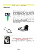
2. How to install the desalinator: 2.2 Motor unit: The HP motor unit should be installed as low as possible in the boat in a horizontal position and it must be protected from water spray as much as possible. The unit is mounted using two alloy brackets under the two motors leaving a few centimetres clear space around the unit, to get sufficient air circulation space for motor cooling. The connection between 1 the prefilter oulet and the inlet to the low pressure side of the 2 pump is in Tricoflex hose of 12mm with doubled stainless jubilee clips at each joint. The HP head of the pump is connected...
Open the catalog to page 7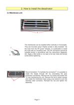
2. How to install the desalinator: 2.4 Membrane unit 1 The membranes can be installed either vertically or horizontally. 1 They are mounted using 4 Parker screws in alloy brackets . As 2 the hose from the HP pump vibrates, it is preferable to install the hose with an insulating tube. The HP connectors should be installed strictly in accordance with the instructions (Appendix A2). Apply a little loctite or nut seal to the two male and female cones before tightening. 2 3 3 Recommendation: To facilitate the connection , it is possible to rotate the heads through 90° by unscrewing the grey production...
Open the catalog to page 8
2. How to install the desalinator: 2.5 Control panel: 1 2 6 3 5 7 1 8 4 2 The control panel must be mounted on a vertical surface as close as possible to the motor / pump unit and to the membranes. Leave space behind the panel to facilitate the connections. It is recommended that it is installed at the bottom or on the sides of cupboards, under chart table or main cabin seats, on the front panel of a rear bunk, … The panel has the following water connections: 1 HP pipe exiting the membranes (blue mark) 2 Production hose exiting the membranes (blue hose) 3 Production hose from panel to tanks :...
Open the catalog to page 9
3. Starting the Dessalator : 1. Ensure the valves are open before starting up the desalinator (Hull valve and waste oulet valve if relevant) 2. If the desalinator has not been run for several days rinse with the three-way valve on the pre-filter as for normal rinsing before use. This should be carried out while the desalinator is idle and with the pressure regulator open (fully anti-clockwise). Rinse for two minutes. 3. To start the desalinator, the pressure regulator must be open. Switch on. 4. Turn the pressure regulator dial to the right, until the HP gauge reading is in the orange zone then...
Open the catalog to page 10
4. Directions for use: MEMBRANES DELICATE COMPONENTS Reverse osmosis membranes must be carefully maintained as they are the most delicate elements of the reverse osmosis system. We recommend that the maintenance instructions are carefully followed to prevent the membranes from damage and to ensure the guarantee is not invalidated. Maximum production capacity of the desalinator is achieved with a sea water temperature of 25°C. The functioning of the membranes will vary depending on the temperature of the sea water. Output drops by approximately 2.5% to 5% for each degree below 25°C. Extreme temperatures:...
Open the catalog to page 11All Dessalator catalogs and brochures
 Commercial Brochure
24 Pages
 DC Freedom 60
21 Pages
 AC CRUISE 100
1 Page
 D90 PRO 230 or 400V
1 Page
 DC Freedom 30
22 Pages
 AC CRUISE 60
1 Page
 Freedom 100
1 Page
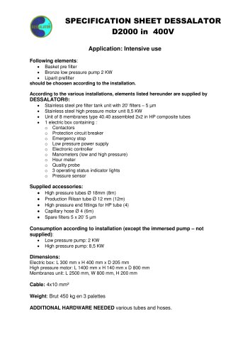 D2000 SPE
1 Page

Archived catalogs
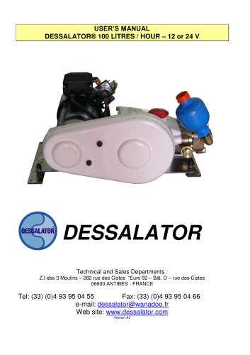 D 100
D 10021 Pages
 DUO 60
21 Pages
 D 60
D 6022 Pages
 DUO 100
21 Pages
 D440-D1000
16 Pages
 D90 - D 280 REMOTE CONTROL
22 Pages
 D 90 TO D 280
21 Pages
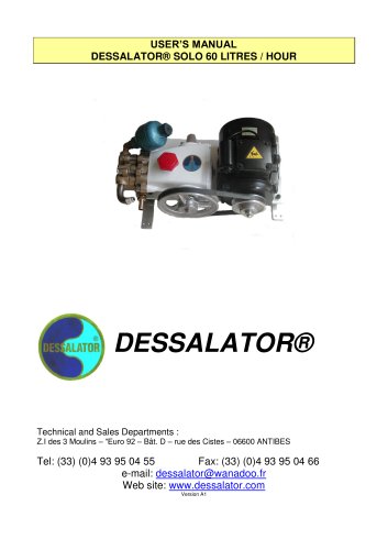 SOLO 60
19 Pages