Catalog excerpts

USER'S MANUAL REMOTE CONTROL VERSION COMPACT VERSION Technical and Sales Departments: Z.I des 3 Moulins - « Euro 92 » - Bât. D - rue des Cistes - 06600 ANTIBES e-mail: contact@dessalator.com
Open the catalog to page 1
Remote control - Horizontal version page 1 Remote control-Vertical version page 2 Integrated control - Compact version page 3 2. Components supplied by DESSALATOR page 4 3.1 Sea water inlet valve and filters page 5 3.2 Pre-pump and high pressure switch page 6 3.4 Control panels page 8 3.5 Motor unit page 9 3.6 Connection plan page 10 3.7 High pressure connectors page 11 5. Reverse osmosis principle page 13 6.1 Cleaning the membranes page 15 6.2 Sterilizing the membranes page 16 7. Instructions for sterilisation of cartridges page 17 8. Automatic Rinsing page 18
Open the catalog to page 2
_ACCORDING TO WATERMAKER TYPE: Hull valve: The VA hull valve strainer filters out the larger particles Pre-pump: (with exception of "Solo" model) Fixed under the waterline it enables water to flow through the pre-filters to the HP motor unit. Pre-filters (One filter for "solo" model): The first 25um cartridge filters out rough particles and the second 5um cartridge refines the treatment. For automatic rinsing an electro-valve is mounted. Motor unit: HP motor unit either in compact frame or with remote control. It allows water to be pressurised to 60-65 bars. Motor with integrated control...
Open the catalog to page 6
DESALINATOR 90 TO 280 LITRES / HOUR Sea water inlet valve %: The sea water inlet valve should be positioned as low as possible below the waterline and should be accessible. The grooves on the strainer should be facing forward (towards the bow) for maximum water intake when the boat is moving forward. The underwater installation should be sealed with Rubson or Sicaflex. The valve and the hose connector can be installed using a tube made watertight with 577 loctite The sea water inlet valve should be connected to the pre-filter using a Tricoflex hose 19 mm inner diameter, with 2 stainless...
Open the catalog to page 7
DESALINATOR 90 TO 280 LITRES / HOUR The pre-pump with its rinse valve3 (with exception of "Solo" version) should be installed as low as possible in the boat and should be easily accessible. The pressurised fresh water pipe should be connected to the valve to facilitate rinsing the desalinator. See water and electricity connection plan enclosed (page 10). Recommendation: Remember to attach two stainless jubilee clips to each joint. THE PUMP SHOULD NOT BE PLACED WHERE THERE IS A RISK OF WATER SPRAY. Pump cable case 220V Pump cable case 380V CAUTION: POWER SUPPLY SHOULD BE SWITCHED OFF BEFORE...
Open the catalog to page 8
DESALINATOR 90 TO 280 LITRES / HOUR Membrane(s) according to desired water flow: 1 membrane for 90 litres / hour water production 2 membranes for 160 litres / hour water production 3 membranes for 200 litres / hour water production 4 membranes for 280 litres / hour water production The membranes can be installed either vertically or horizontally. They are mounted using 4 Parker screws in alloy brackets1. The number of membranes used depends on the desired water flow. Hose from the HP pump should join the membranes at the red ring2. As the hose from the HP pump vibrates, it is preferable...
Open the catalog to page 9
DESALINATOR 90 TO 280 LITRES / HOUR Control panels in accordance with your watermaker version: Horizontal version: Vertical Version: Front panel Back panel Front panel Back panel Compact version: Front panel Back panel All remote control panels must be mounted on a vertical surface. Installing the panels close to the watermaker system facilitates the piping Figures for each connection are as follows: (see diagrams page 1, 2 and - N°8 (blue): HP piping exiting the membranes. - N°6 (blue hose 8/10mm diameter) production hose exiting the - N°3: Production hose from panel to tanks. A 10mm inner...
Open the catalog to page 10
DESALINATOR 90 TO 280 LITRES / HOUR There are three water connections to the pump head: - A 15mm diameter pipe1 from the pre-filters. - A HP hose2 to the 8mm diameter membranes (see installation - A capillary 3mm diameter tube3: this must be clipped into its connector. To remove it, just push the black ring and remove at the same time. The HP unit should be installed in a horizontal position and must be protected from water spray. Connections are illustrated Additional hardware needed for assembly: - miscellaneous screws (including Parker) - assortment of stainless jubilee clips 10mm, 16mm...
Open the catalog to page 11
DESALINATOR 90 TO 280 LITRES / HOUR 3.7 INSTALLATION INSTRUCTIONS - HP CONNECTORS 1. Screw the brass union (skirt) anti-clockwise onto the HP pipe, no more than 2.5cm. Stop where the inner threading disappears. 2. Insert the steel tapered end-piece into the stainless steel nut, and tighten very firmly on the male tapered union. 3. Lightly grease the tip of the stainless steel cone and screw it perfectly straight into the brass union. Stop where the steel threading disappears into the brass end-piece (a gap of approximately 7mm between the nut and the brass union)
Open the catalog to page 13
1. Ensure the valves are open before starting up the desalinator. 2. If the desalinator has not been run for several days, rinse with the three-way valve on the pre-pump as for normal rinsing before use. This should be carried out while the desalinator is idle and with the pressure regulator open (fully anti- clockwise). Rinse for two minutes. 3. To start the desalinator, the pressure regulator must be open. Switch on: the low pressure pump will start than the high pressure pump will automatically start. 4. Turn the pressure regulator dial to the right, until the HP gauge reading is in the...
Open the catalog to page 14
5. REVERSE OSMOSIS PRINCIPLE What is the reverse osmosis principle used in your desalinating system? Sea water is forced at high pressure through the membranes which act as "molecular sieves", only allowing pure fresh water to pass through. Most dissolved solid particles will not penetrate the membranes. This waste, along with the remaining saline solution, will flow on the surface of the membranes and will be rejected. Not all particles dissolved in sea water can be eliminated. The system is designed to reject 99% of the TDS (Totally Dissolved Solids); approximately 2% of the 35,000...
Open the catalog to page 15All Dessalator catalogs and brochures
-
Commercial Brochure
24 Pages
-
DC Freedom 60
21 Pages
-
AC CRUISE 100
1 Pages
-
D90 PRO 230 or 400V
1 Pages
-
DC Freedom 30
22 Pages
-
AC CRUISE 60
1 Pages
-
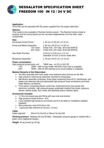
Freedom 100
1 Pages
-
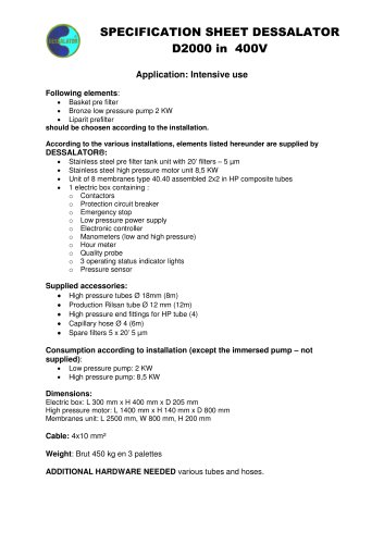
D2000 SPE
1 Pages
Archived catalogs
-
DUO 100
21 Pages
-
DUO 60
21 Pages
-
D 60
22 Pages
-
D 100
21 Pages
-
D440-D1000
16 Pages
-
D90 - D 280 REMOTE CONTROL
22 Pages
-
SOLO 100
19 Pages
-
SOLO 60
19 Pages


