GPU -3
1 /17Pages

GPU -3
1 /17Pages
Catalog excerpts

Generator Protection Unit Data sheet
Open the catalog to page 1
Generator protection (ANSI) Busbar protection (ANSI) General information The Generator Protection Unit, GPU-3, is a compact microprocessor-based protection unit containing all necessary functions for protection of a synchronous/asynchronous generator. It contains all necessary galvanically separated 3-phase measuring circuits. The GPU-3 is intended for land- and marine-based applications. It is well-suited for PLC-controlled systems, and the interfacing can be done via digital and analogue I/Os or via serial communication. Display unit The display unit is separate and can be installed directly...
Open the catalog to page 3
Engine control and protection With the engine control and protection option added, the GPU-3 will control the start and stop sequences of the engine and furthermore it can be used as engine protection unit providing full backup of engine shutdown channels in case the main processor fails. The option includes an engine interface I/O card with separate power supply and processor. The card is equipped with the following I/Os: Available Multi-inputs (with wire break) Digital inputs MPU input w/wire break Start prepare relay Starter relay Stop coil w/wire break INFO The number in parenthesis indicates...
Open the catalog to page 4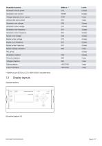
Protection function Generator reverse power Generator over-current Voltage-dependent over-current Inverse time over-current Generator over-voltage Generator under-voltage Generator over-frequency Generator under-frequency Busbar over-voltage Busbar under-voltage Busbar over-frequency Busbar under-frequency Busbar voltage unbalance Generator overload Current unbalance Voltage unbalance * (ANSI# as per IEEE Std. C37.2-1996 (R2001) in parenthesis). Display layouts Standard delivery Generator Protection Unit Power Self check
Open the catalog to page 5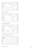
Generator Protection Unit Power Self check BACK LOCAL Engine control (option Y7) Generator Protection Unit Power Self check BACK STOP Engine and GB control (option Y1) Generator Protection Unit Power Self check BACK STOP Additional operator panel - AOP-1 (option X3)
Open the catalog to page 6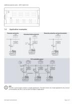
Additional operator panel - AOP-2 (option X4) Application examples Generator protection Generator protection and synchronisation Generator/mains protection PLC-controlled system Disp lay 1 INFO The GPU-3 can be used in simple or complex applications. The above shows very simple applications only, but due to the flexibility, the GPU-3 can be used in all types of applications.
Open the catalog to page 7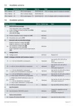
Available variants One 3 m display cable is included as standard One 3 m display cable is included as standard Available options Slot no. Option type Mains protection package Time-dependent under-voltage (27t) Under-voltage and reactive power low (27Q) A1 Vector jump (78) df/dt (ROCOF) (81) A4 Positive sequence (mains voltage low) (27) Generator add-on protection package Negative sequence voltage high (47) Negative sequence current high (46) Zero sequence voltage high (59) C2 Zero sequence current high (50) Power-dependent reactive power import/export (40) Voltage control D1 Voltage control E...
Open the catalog to page 8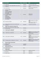
Option Description Slot no. Option type Engine comm.: MTU (ADEC/MDEC) and CAN bus 8 J1939 (H7) CAN bus (J1939): Caterpillar Cummins CM850/570 Detroit Diesel (DDEC) Deutz (EMR) Iveco (NEF/CURSOR) H7 John Deere (JDEC) Perkins Scania (EMS) Scania (EMS S6) Volvo Penta (EMS) Volvo (EMS2) Engine control and protection (safety system) OR I/O extension 13 binary inputs, configurable 4 relay outputs, configurable Modbus RTU/ASCII (RS-232) and GSM modem connection Engine control, digital and analogue I/Os M13.X 7 digital inputs, configurable M14.X 4 relay outputs, configurable M15.X 4 analogue inputs,...
Open the catalog to page 9
(ANSI# as per IEEE Std. C37.2-1996 (R2001) in parenthesis). INFO Notice that not all options can be selected for the same unit. Refer to the paragraph "Hardware overview" in this data sheet for further information about the location of the HW options in the unit. Available accessories Standard Display Unit, DU-2 For connection directly to base unit with display cable Specify product and folio (refer to paragraph "Display layouts") Additional Display Unit, DU-2 (X2) For CAN bus connection to the standard display Two additional displays can be used with each GPU unit Additional Operator Panel,...
Open the catalog to page 10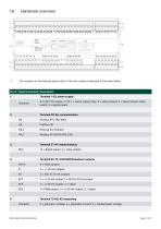
Hardware overview Service port Power Self check ok Alarm inhibit The numbers in the drawing above refer to the slot numbers indicated in the table below. Slot # Option/standard Description 1 Terminal 1-28, power supply Standard 8 to 36 V DC supply, 11 W; 1 × status output relay; 5 × relay outputs; 2 × pulse outputs (kWh, kvarh); 5 × digital inputs 13 × digital inputs; 4 × relay outputs Terminal 65-72, GOV/AVR/transducer outputs M14.4 1 × PWM output; 1 × +/-20 mA output; 2 × relays Terminal 73-89, AC measuring Standard 3 × generator voltage; 3 × generator current; 3 × busbar/mains voltag
Open the catalog to page 11
Slot # Option/standard Description 6 8 to 36 V DC supply, 5 W; 1 × magnetic pickup (MPU); 3 × multi-inputs; 7 × digital inputs, configurable; 4 × relay outputs Terminal 126-133, engine communication, inputs/outputs H5 LED I/F Display connection; service port (USB); power LED; self check LED; alarm inhibit LED; EtherNet (option N) LED EtherNet - Modbus TCP/IP - EtherNet/IP - SMS/e-mail alarms INFO There can only be one hardware option in each slot. It is for example not possible to select option H2 and option H3 at the same time, because both options require a PCB in slot #2. INFO Besides the...
Open the catalog to page 12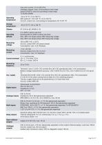
Fast over-current: 3 % of 350 %*In Analogue outputs: class 1.0 according to total range Option EF4/EF5: class 4.0 according to total range To IEC/EN 60688 Operating temperature -25 to 70 °C (-13 to 158 °F) With option N: -25 to 60 °C (-13 to 140 °F) (UL/cUL Listed: max. surrounding air temperature: 55 °C/131 °F) Storage temperature Operating altitude 0 to 4000 m above sea level Derating 2001 to 4000 m above sea level: Max. 480 V AC phase-phase 3W4 measuring voltage Max. 690 V AC phase-phase 3W3 measuring voltage Measuring voltage 100 to 690 V AC +/-20 % (UL/cUL Listed: 600 V AC phase-phase) Consumption:...
Open the catalog to page 13All DEIF catalogs and brochures
 AWC 400
36 Pages
 AKR 3
AKR 310 Pages
 AGC 150 ATS
4 Pages
 AFC plant management
18 Pages
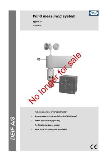 Wind measuring system
4 Pages
Archived catalogs
 AMC 600
38 Pages
 Insulation monitors, AAL-2
6 Pages
 DBC-1
DBC-113 Pages


- Analog indicator
- Boat monitoring and control panel
- Ship software
- Digital indicator
- Ship control panel
- Ship indicator
- Rudder angle indicator
- Motor monitoring panel
- Boat relay
- Touch screen control panel
- Alarm control panel
- Signal converter
- Ship alarm and safety system
- Wind vane anemometer
- Ship relay
- LED indicator
- Multi-function indicator
- Ship converter
- Analog converter
- Electrical circuit relay