DBC-1
1 /13Pages

DBC-1
1 /13Pages
Catalog excerpts

DATA SHEET DBC-1 DEIF Battery Charger
Open the catalog to page 1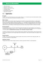
Overvoltage protected Boost/equalisation functionality Failure alarm functionality DC supply The DBC-1 can be used as DC supply due to the low ripple of maximum 1.3 %. Automatic recovery and protection against overload, short circuit and reverse polarity are standard functionalities of the DBC-1. Battery charger DBC-1 is ideal for the use as battery charger. The general recommendation for charging lead (Pb) batteries is a voltage ripple of maximum 2-5 %, where the maximum voltage ripple for DBC-1 is 1.3 %. It is designed to charge both lead-acid and gel batteries. The recommended charge voltage...
Open the catalog to page 3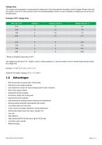
Voltage drop The charger can be adjusted to compensate the voltage drop in the wiring between the battery and the charger. Please notice that the current is only 50 % of the nominal current if the boost/equalisation function is used. Examples of voltage drop can be found in the table below. Example of DC voltage drop Wire size, mm2 * Based on threaded copper wire at 20°C. The voltage drop formula is: dV = length x current x cable resistance x 2, thus the double current or double length will also double the voltage drop. Example: 1.5 mm2, 5 m, 10 A => dV = 1.2 V Setting for Pb battery charging:...
Open the catalog to page 4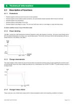
Protected against continuous short-circuit and no-load operation Protected against reverse battery polarity connection, and automatically restarts operation after the fault is removed Protected against over-temperature Protected against undervoltage on line input Protected against overvoltage on output. The unit shuts itself down when an overvoltage on output terminals arises. An alarm condition occurs in any of the above cases. Power derating The DBC-1 series has a high temperature protection designed to allow safe operation at all times. The power output derates above 60°C of ambient temperature...
Open the catalog to page 5
The alarm contact is steady open when: • Failure on the line input or input fuse The alarm contact will work intermittent when: • Failure caused by battery reverse polarity connection Overvoltage condition on output terminals. (Note: when overvoltage is detected while battery is connected, the alarm relay is open and locked in this position until the battery is disconnected) LED indication and alarm relay status Alarm relay Normal operation Short circuit on output Reverse polarity connection Switching open/closed *) High temperature/power derating No input voltage with battery connected No input...
Open the catalog to page 6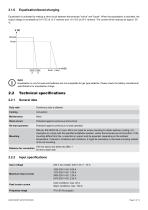
Equalisation is activated by making a short circuit between the terminals "minus" and "boost". When the equalisation is activated, the output voltage is increased by 0.8 V DC at 12 V versions and 1.6 V DC at 24 V versions. The current will be reduced by approx. 50 %. Inom Imax INFO Equalisation is only for lead-acid batteries and not acceptable for gel type batteries. Please check the battery manufacturer specifications for equalisation charge. Technical specifications General data Duty ratio Continuous duty is allowed Protected against continuous short-circuit No-load operation Protected against...
Open the catalog to page 7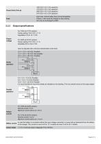
1205 230 V AC: 0.43 capacitive 1210 230 V AC: 0.43 capacitive 2405 230 V AC: 0.55 capacitive 2410 230 V AC: 0.54 capacitive Input fuse: internal safety fuse (not exchangeable). If blown, it will cause the charger to stop working. Can only be exchanged by DEIF. Output specifications For 1205 and 1210 versions: Factory setting 13.8 V DC +/-1 % Adjustable 12.6 to 15.1 V DC Output voltage For 2405 and 2410 versions: Factory setting 27.6 V DC +/-1 % Adustable 25.2 to 30.2 V DC (Can be adjusted with a trimmer potentiometer at the front) 12 V + 12 V = 24 V DC: Possible 12 V + 24 V = 36 V DC: Not possible...
Open the catalog to page 8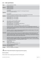
Other specifications Line regulation: All products have output regulation of maximum 1% in the range of line input of 230 V AC models: 230 V AC ±15 % Load regulation: All products have output load regulation of maximum 1 % in the range of no load to full load. <2 ms at a load distribution of 10 to 90% from rated current, peaks <2 % IEC/EN 61000-6-4 vers. 115 V and 230 V IEC/EN 61000-6-1 vers. 115 V and 230 V IEC/EN 61000-6-2 vers. 115 V and 230 V RFI suppression: According to EN55011 class B Static discharge ESD: 4 kV contact discharge IEC/EN 61000-4-2: 8 kV free air discharge Electromagnetic...
Open the catalog to page 9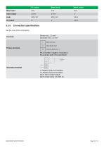
Boost input Alarm output Mains input Alarm output Connection specifications See the cover of the unit (imprint). Primary terminals - Mains Line input. - Mains Neutral input. - Protective Earth input. PE on the DBC-1 must be connected to the protective earth of the switchboard. TO BATTERY BOOST ALARM Secondary terminals (-): Negative output to the battery (+): Positive output to the battery Alarm: Alarm contact outputs Alarm contact rating: 3 A 250V AC.
Open the catalog to page 10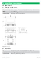
Top cover is plastic consisting of polycarbonate and bottom part is aluminum alloy. Dimensions (WxHxD) Top cover is plastic consisting of polycarbonate and bottom part is aluminum alloy. Dimensions (WxHxD)
Open the catalog to page 11
Order specifications Type - output voltage - output current - supply Example: DBC-1 - 24 V DC - 5 A - 230 V AC DEIF A/S reserves the right to change any of the contents of this document without prior notice. The English version of this document always contains the most recent and up-to-date information about the product. DEIF does not take responsibility for the accuracy of translations, and translations might not be updated at the same time as the English document. If there is a discrepancy, the English version prevails.
Open the catalog to page 13All DEIF catalogs and brochures
 AWC 400
36 Pages
 AKR 3
AKR 310 Pages
 AGC 150 ATS
4 Pages
 AFC plant management
18 Pages
 Wind measuring system
4 Pages
Archived catalogs
 AMC 600
38 Pages
 GPU -3
17 Pages
 Insulation monitors, AAL-2
6 Pages


- Analog indicator
- Boat monitoring and control panel
- Ship software
- Digital indicator
- Ship control panel
- Ship indicator
- Rudder angle indicator
- Motor monitoring panel
- Boat relay
- Touch screen control panel
- Alarm control panel
- Signal converter
- Ship alarm and safety system
- Wind vane anemometer
- Ship relay
- LED indicator
- Multi-function indicator
- Ship converter
- Analog converter
- Electrical circuit relay