AWC 400
1 /36Pages

AWC 400
1 /36Pages
Catalog excerpts

AWC 400 Advanced Wind Turbine Controller DATA SHEET ● Applicable for offshore or nearshore environments ● Unrivalled robustness – 5-year warranty ● Open programming in ANSI C/C++ and IEC61131-3 DEIF A/S · Frisenborgvej 33 · DK-7800 Skive · Tel.: +45 9614 9614 · Fax: +45 9614 9615 · [email protected] · www.deif.com
Open the catalog to page 1
2. Power and Control Module 3. Distributed I/O and field bus controller 4. Input and Output Module 5. Grid Protection Module 6. Serial Synchronous Interface 7. Base mounting racks 8. Wind Turbine Application Development
Open the catalog to page 2
SHORT CT BEFORE DISCONNECTING TERMINAL 1 ... 6 Operating temperature Storage temperature Reference temperature Temperature Temperature Technical specifcations Sp AWC 400 data sheet 4921240388 UK AWC 400 base unit 1.1 About the base unit 1.1.1 System specifications The AWC 400 is designed as a highly flexible, modular process controller covering the special demands of wind power plants in terms of reliability, robustness and flexibility. Protection class Plastic headers acc. UL94-V0, Al-case, steel cover plate
Open the catalog to page 3
AWC 400 data sheet 4921240388 UK Power and Control Module The PCM 4-3 module is the main CPU in the AWC 400 series which hold the application for the wind power plant. The PCM 4-3 module includes the most used field buses for easy integration og communication interfaces in a given application. Power and control module Power supply
Open the catalog to page 4
Power and Control Module Digital input + Supply - Supply + Supply - Supply Power ARCNET * Cable end termination resistor E.G. 120 Ω ** Do not connect both RS 485 ports. Either terminal 13,14,15 or 19, 20, 21 DATA +(A) * DATA -(B) Shield Do not connect DATA +(A) DATA -(B) Shield Do not connect DATA +(A) * DATA -(B) Do not connect CAN-H * CAN-L Shield Do not connect
Open the catalog to page 5
AWC 400 data sheet 4921240388 UK Power and Control Module
Open the catalog to page 6
AWC 400 data sheet 4921240388 UK Power and Control Module
Open the catalog to page 7
Distributed I/O and field bus controller 3. Distributed I/O and field bus controller 3.1 PCM 4∙4 3.1.1 PCM 4∙4 module specifications The PCM 4∙4 module is typically used as a distributed controller in a wind power plant. Digital relay output (NO) 250VAC/24VDC 8A Digital input designed for potential-free contacts. Open/Close 5V/7.5mA 3 x CAN: Independent CAN bus lines 125/250kbps 1 x RS422/485 port: 9,600 – 57,600 Baud 1 x ARCNET port either electrical or optical connection: 4,800 – 57,600 Baud 1 x Display port (TTL): 4,800 – 57,600 baud USB service interface 256,000 Baud Power supply Power ARCNET...
Open the catalog to page 8
Distributed I/O and field bus controller Digital input + Supply - Supply + Supply - Supply Power ARCNET * Cable end termination resistor E.G. 120 Ω ** Do not connect both RS 485 ports. Either terminal 13,14,15 or 19, 20, 21 DATA +(A) * DATA -(B) Shield Do not connect DATA +(A) DATA -(B) Shield Do not connect DATA +(A) * DATA -(B) Do not connect CAN-H * CAN-L Shield Do not connect
Open the catalog to page 9
AWC 400 data sheet 4921240388 UK Distributed I/O and field bus controller
Open the catalog to page 10
AWC 400 data sheet 4921240388 UK Distributed I/O and field bus controller
Open the catalog to page 11
Input and Output Module 4. Input and Output Module 4.1 IOM 4∙2 4.1.1 IOM 4∙2 module specifications IOM 4∙2 is a highly flexible IO module which holds the most commonly used IO signals used in a wind power plant. IOM 4∙2 is designed for the rough environment in a wind turbine and all input and output are protected by optical insulation from other potentials. 9…36V DC or -9…-36V DC with reference to common. Optically insulated from other potentials 550V AC 40 channel multi-function I/O module with analogue inputs, temperature inputs, digital inputs, frequency counter inputs, analogue outputs and...
Open the catalog to page 12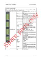
Input and Output Module - continued from previous page 40 channel multi-function I/O module with analogue inputs, temperature inputs, digital inputs, frequency counter inputs, analogue outputs and digital outputs PT100, PT1000 or NiCr-Ni thermocouple sensor -50 to 200°C for PT sensors; -50 to 1000°C for NiCr-Ni sensors Cable error Open input and short circuit are detected. (Only open for NiCr-Ni sensors) 0.5°K at reference temperature. 2.0°K at operational temperature. 1.0°K at reference temperature. 2.5°K at operational temperature (2-wire only when cables are shorter than 1m). Accuracy (NiCr-Ni...
Open the catalog to page 13
Input and Output Module
Open the catalog to page 14
Input and Output Module
Open the catalog to page 15
AWC 400 data sheet 4921240388 UK Input and Output Module
Open the catalog to page 16
AWC 400 data sheet 4921240388 UK Input and Output Module
Open the catalog to page 17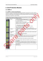
AWC 400 data sheet 4921240388 UK Grid Protection Module The GPM 4-1 module is a class 0.5 grid measurement and protection module which can be fully configured from the main application. All measurements are available for the main application each period of the connected grid. Two relay outputs can be controlled by any of the protection functions to secure a fast and reliable disconnection of a generator or other purposes. 3-phase Grid and Generator Voltage and Current measurement(Class 0.5) with configurable grid protection features like vector jump(A^) detection
Open the catalog to page 18
Grid Protection Module Voltage grid SHORT CT BEFORE DISCONNECTING TERMINAL 1 ... 6
Open the catalog to page 19
AWC 400 data sheet 4921240388 UK Grid Protection Module AWC 400 data sheet 4921240388 UK Grid Protection Module
Open the catalog to page 20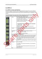
AWC 400 data sheet 4921240388 UK Grid Protection Module The GPM 4-2 module is a class 0.5/1.0 AC/DC voltage measurement module which can be fully configured from the main application. All measurements are available for the main application. Two relay outputs can be controlled by any of the protection functions to secure a fast and reliable disconnection of a generator or other purposes. 3-phase Grid Voltage measurement (class 0.5) with configurable grid protection features like 'ectoi jump (A9) detection, and 3 individually separated High Voltage DC inputs.
Open the catalog to page 21
Grid Protection Module
Open the catalog to page 22
Grid Protection Module Relay output
Open the catalog to page 23
AWC 400 data sheet 4921240388 UK Grid Protection Module
Open the catalog to page 24
Serial Synchronous Interface 6. Serial Synchronous Interface 6.1 SSI 4∙1 6.1.1 SSI 4∙1 module specifications Serial Synchronous Interface module with RS485 port and SSI to CAN converter Power supply 6 x SSI channels: 125/250/1000kHz SSI frequency 8-32 bit resolution 50us-50ms frame delay Frame error, wire break and sensor specific error detection Gray or binary code conversion 24VDC supply output, max. 50mA per encoder SSI 4∙1 is an interface module which supports SSI encoders and one RS485 interface port. All information from the SSI and RS485 is available through the CAN interface. SSI 4∙1...
Open the catalog to page 25All DEIF catalogs and brochures
 AKR 3
AKR 310 Pages
 AGC 150 ATS
4 Pages
 AFC plant management
18 Pages
 Wind measuring system
4 Pages
Archived catalogs
 AMC 600
38 Pages
 GPU -3
17 Pages
 Insulation monitors, AAL-2
6 Pages
 DBC-1
DBC-113 Pages


- Analog indicator
- Boat monitoring and control panel
- Ship software
- Digital indicator
- Ship control panel
- Ship indicator
- Rudder angle indicator
- Motor monitoring panel
- Boat relay
- Touch screen control panel
- Alarm control panel
- Signal converter
- Ship alarm and safety system
- Wind vane anemometer
- Ship relay
- LED indicator
- Multi-function indicator
- Ship converter
- Analog converter
- Electrical circuit relay