AMC 600
1 /38Pages

AMC 600
1 /38Pages
Catalog excerpts
DATA SHEET AMC 600 Programmable Automation Controller with EtherCAT based I/O modules
Open the catalog to page 1
The AMC 600 is designed as a highly flexible, modular PLC and I/O system covering the special demands of for example wind power plants in terms of reliability, robustness and flexibility. EtherCAT is used as native communication protocol, as the backplane communication, and as interconnection between multiple AMC 600 racks via electrical or fiber optical connections. Other DEIF EtherCAT I/O modules or third party EtherCAT I/O modules can also be connected. Disclaimer DEIF A/S reserves the right to change any of the contents of this document without prior notice. The English version of this document...
Open the catalog to page 3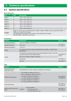
System specifications Rack dimensions Rack Size (HxDxW) Rack6‧10: The rack have one slot reserved for a SIM6‧1, SIM6‧2 or SIM6‧3, one slot reserved for PDM6‧1 or PDM6‧2, and 8 slots for I/O modules. The default rack named Rack6‧10 has 10 slots in total, hereof 8 for I/O modules. Note that PCM6‧1 occupies both slot 3 and 4. Environment Category Operating temperature Storage temperature Reference temperaure Up-to 4000 m without de-rating (for deployment above 4000 m, contact Product Management). All modules are conformal coated, hence protected against moisture, mold, dust, IEC 60068-2-30 corrosion...
Open the catalog to page 4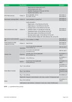
Signal input and output ports: ±2 kV Duration each polarity: 1 min. Level extended to: Contact 6 kV Main power supply: ±3 kVp DM and ±3 kVp CM Dig output power supply: ±3 kVp DM and ±3 kVp CM • Slow transients test, surge RF common mode conducted Criteria: A test Power frequency H-field (magnetic) immunity Vibration Test Shock (Base mounted) Tested with 3 impacts in each direction in all 3 axes, a total of 18 impacts per test 25 g, 16 ms, half sine 1,000 bumps in each direction, 2 directions in each axis, a total of 6,000 bumps NOTE g = gravitational force (g-force).
Open the catalog to page 5
Safety and protection Category Installation (over-voltage) category III, 600 V, pollution degree 2 Aluminium case and cover plates (all plastic parts are self-extinguishing) Approvals These approvals apply to the controller rack (with all the modules properly installed). Standards CE UL/ULC Recognized component to UL/ULC to UL6200:2019 1st edition
Open the catalog to page 6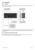
When the AMC 600 is installed in an enclosure, we recommend to have free space above and below the cabinet for at least 50 mm in order to ensure sufficient ventilation. Lifetime is affected by temperature, and we recommend to install and operate forced ventilation if enclosure temperature is above 40 °C. Lowering the temperature by 10 °C will double the estimated lifetime. Keep other heating elements in the same enclosure away from the AMC 600. Separation: Noisy modules and cables When noisy modules (i.e. inverters) are placed in the same cabinet we recommend to place power and motor cables in...
Open the catalog to page 7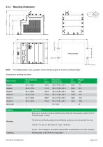
Mounting dimensions Drilling template * * The drilling template is only a guideline. Use the dimensions given to create your drilling template. Dimensions for mounting the cabinet: Rack version Blind plate Specification Base mount, using four stainless steel M6 screw bolts with matching plain washer of A2-70 ISO 3506 quality or better. The bolts and self-locking washers (or self-locking screws) are not included with the rack. UL/ULC : For use on a flat surface of a type 1 enclosure UL/ULC : To be installed in accordance with the NEC (United States) or the CEC (Canada). Mounting bolts : 5 Nm (45...
Open the catalog to page 8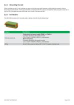
When mounting the rack it is very important to make sure that the metal rack frame gets a solid electrical connection with the presumed grounded cabinet. A firmly grounded Rack is important both with a view to crew/operator safety precautions, and also in order to form a complete grounded metal cage, which is part of the approved EMC. The AMC 600 terminals are of removable push-in spring connectors of grip fastened type: Terminal connections Frame ground and power supply (PDM6‧1 or PDM6‧2): Connectors (terminals): See specific module 0.2 to 2.5 mm2 ( AWG24 to AWG12 ), multi-stranded Other connections:...
Open the catalog to page 9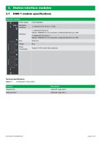
3. Station interface modules 3.1 EtherCAT interface Power supply From backplane 1 x EtherCAT OUT (Port 3) - LVDS 1 x EtherCAT IN (Port 0) Optical: 100BASE-FX, SC connectors, multimode fibre 62.5 µm, OM1 1 x EtherCAT OUT (Port 1) Optical: 100BASE-FX, SC connectors, multimode fibre 62.5 µm, OM1 Power consumption Typical 3.5 W (2 active fibre channels) Terminal specifications Table 3.1 Configuration: Slave station EtherCAT Logic Port 0 EtherCAT Logic Port 1
Open the catalog to page 10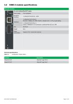
EtherCAT interface For rack holding EtherCAT master Backplane interfaces From backplane 1 x EtherCAT IN (Port 0) - LVDS 1 x EtherCAT OUT (Port 2) Electrical: 100Base-TX, 8P8C (“RJ45”), shielded Cat 5, >0.76 μm gold plating 1 x EtherCAT OUT (Port 1) Optical: 100BASE-FX, SC connectors, multimode fibre 62.5 µm, OM1 25.40 mm Power consumption Typical 2.5 W (1 active fibre channel) Terminal specifications Table 3.2 Configuration: Master station EtherCAT Logic Port 2 EtherCAT Logic Port 1
Open the catalog to page 11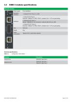
EtherCAT interface Power supply From backplane 1 x EtherCAT OUT (Port 3) - LVDS 1 x EtherCAT IN (Port 0) Electrical: 100Base-TX, 8P8C (“RJ45”), shielded Cat 5, >0.76 μm gold plating Interfaces 1 x EtherCAT OUT (Port 1) Optical: 100BASE-FX, SC connectors, multimode fibre 62.5 µm, OM1 1 x EtherCAT OUT (Port 2) Electrical: 100Base-TX, 8P8C (“RJ45”), shielded Cat 5, >0.76 μm gold plating 25.40 mm Power consumption Typical 2.5 W (1 active fibre channel) Terminal specifications Table 3.3 Configuration: Slave station EtherCAT Logic Port 0 EtherCAT Logic Port 1 EtherCAT Logic Port 2
Open the catalog to page 12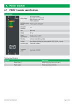
Power module Power supply 30 W power supply Input level: 24 V (18 to 32 V) Black-out hold-up for 10 ms Polarity protection Backplane power Power output to backplane source Backplane interfaces Power consumption Common mode EMI input filter Input galvanic isolated from other potentials, 550 V/50 Hz, 1 minute Connector, grip Connector, screw Terminal specifications Description Power supply input, 24 V (18 to 32 V) Power supply - Power supply input, common
Open the catalog to page 13All DEIF catalogs and brochures
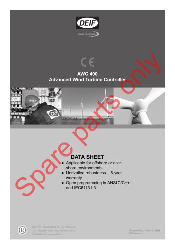 AWC 400
36 Pages
 AKR 3
AKR 310 Pages
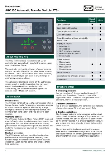 AGC 150 ATS
4 Pages
 AFC plant management
18 Pages
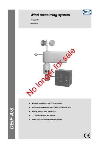 Wind measuring system
4 Pages
Archived catalogs
 GPU -3
17 Pages
 Insulation monitors, AAL-2
6 Pages
 DBC-1
DBC-113 Pages


- Analog indicator
- Boat monitoring and control panel
- Ship software
- Digital indicator
- Ship control panel
- Ship indicator
- Rudder angle indicator
- Motor monitoring panel
- Boat relay
- Touch screen control panel
- Alarm control panel
- Signal converter
- Ship alarm and safety system
- Wind vane anemometer
- Ship relay
- LED indicator
- Multi-function indicator
- Ship converter
- Analog converter
- Electrical circuit relay