
- Catalogs
- Chr. Mayr GmbH + Co. KG
- ROBA-stop® S


ROBA-stop® S
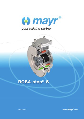
ROBA-stop® S
Catalog excerpts
your reliable partner
Open the catalog to page 1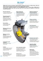
your reliable partner ROBA-stop®-S have two functions. During standard operation they work as holding brakes. When the drives have been switched off, the brakes hold the system safely in position. During critical operational situations, e.g. with EMERGENCY STOP or power failure, ROBA-stop®-S are designed to absorb peak loads with high friction work. These brakes are designed for vertical and horizontal operations. Dust and waterproof Completely enclosed brake design corresponds to Protection IP 67. Permanent protection against corrosion Brake housing and integral terminal box Optimum protection...
Open the catalog to page 2
your reliable partner Quality, Experience, Competence
Open the catalog to page 3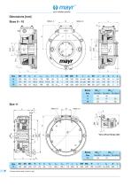
O mayr® your reliable partner 1) Please observe load on shaft or key!
Open the catalog to page 4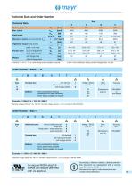
your reliable partner Technical Data and Order Number 2) Tolerance = + 40 % / - 20 %. Other braking torques available on request. 3) ACH = Anti-condensation heating, standard voltages [VAC]: 115; 230. Order Number - Sizes 8 - 10 Terminal box: with terminal 1 with half-wave rectifier 4 with bridge rectifier 5 Options: - Anti-condensation heating - Microswitch for wear monitoring - Other Types available on request Bore Keyway * Standard voltages [VDC]: 24; 104; 180; 207. Permitted voltage tolerance ± 10 % according to DIN IEC 60038. Order Number - Size 11 Additional parts: without additional parts...
Open the catalog to page 5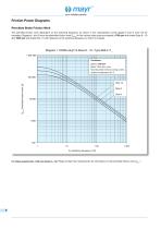
your reliable partner The permitted friction work dependent on the switching frequency, as shown in the characteristic curves (pages 6 and 7) must not be exceeded. Diagrams 1 and 2 show the permitted friction work Qperm for the various brake sizes and speeds (1750 rpm with brake Sizes 8 - 10 and 1000 rpm with brake Size 11) with reference to the switching frequency on which it is based. For higher speeds than 1750 rpm (Sizes 8 - 10): Please contact the manufacturers for information on the permitted friction work Qperm!
Open the catalog to page 6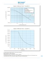
your reliable partner Qperm Permitted friction work [J] Conditions: Speed: 1000 rpm At higher speeds, the friction work reduces acc. diagram 3. Brake 100% duty cycle. Mounting brake without cooling current. Qperm Permitted friction work [J] For higher speeds than 1000 rpm (Size 11): Please observe diagram 3! Design example for a speed of 1250 rpm: Permitted friction work Qperm for 1250 rpm from diagram 3: 300 000 J. This value limits the permitted friction work Qperm acc. diagram 2 for low switching frequencies (here up to 3,5 switchings per hour). The permitted friction work Qperm reduces acc....
Open the catalog to page 7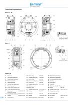
your reliable partner Technical Explanations Sizes 8 - 10 Parts List 1 Gear hub 2 Coil carrier (assembly) 3 Flange plate (assembly) 5 Armature disk (assembly) 6.1 Thrust spring internal pole 6.2 Thrust spring external pole screw (loose in delivery) Screw plug Copper sealing ring Screw plug Copper sealing ring Screw plug Copper sealing ring Sealing cover Brake plate Hexagon head screw O-ring Distance washer (21.1 Cap screw) Microswitch (assembly) Heating (assembly) (option) Type tag Cable gland Housing Adjusting plate (28.1 Cap screw) Washer DIN 7349 Hexagon head screw DIN EN ISO 4017 Flange plate...
Open the catalog to page 8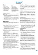
your reliable partner • Release monitoring • Emergency hand release • Terminal block • Condensation drain screw • Corrosion protection • Wear monitoring • Bracket hand release • Built-in rectifier • Anti-condensation heating • Tacho attachment possibility (standard on Sizes 8 - 10) • Available without flange plate (only on Size 11) The following points must be observed before installing the - The eccentricity of the shaft end in relation to the mounting pitch circle must not exceed 0,4 mm. - The run-out deviation of the screw-on surface to the shaft must not exceed the permitted run-out tolerance...
Open the catalog to page 9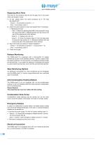
your reliable partner The rotor (4), the armature disk (5) and the gear hub (1) are parts which are subject to wear. 1) At first, please follow the same procedure as in “Air Gap Re-Adjustment”: - Sizes 8 - 10 according to points 1 - 4 - Size 11 according to point 1 2) Check the parts subject to wear and replace them if necessary. • Replacing the rotor: - Size 11: Attach the adjusting plate (28) to the housing (27) using the cap screws (28.1). (Adjusting plate and cap screws are part of the replacement rotor delivery). - Sizes 8 - 11: Replace the rotor (4). - Sizes 8 - 10: Screw the distance rings...
Open the catalog to page 10
your reliable partner Guidelines on the Declaration of Conformity: A conformity evaluation has been carried out for the product (electromagnetic safety brake) according to the EC Low Voltage Directive 2006/95/EC. The conformity evaluation is set out in writing in a separate document and can be requested if required. The product cannot be operated independently according to the EMC Directive. Due to their passive state, brakes are also non-critical equipment according to the EMC. Only after integration of the product into an overall system can this be evaluated in terms of the EMC. For electronic...
Open the catalog to page 11
Headquarters Chr. Mayr GmbH + Co. KG Eichenstraße 1, D-87665 Mauerstetten Tel.: +49 83 41/8 04-0, Fax: +49 83 41/80 44 21 www.mayr.com, E-Mail: [email protected] your reliable partner China Mayr Zhangjiagang Power Transmission Co., Ltd. Fuxin Road No.7, Yangshe Town 215637 Zhangjiagang Tel.: 05 12/58 91-75 67 Fax: 05 12/58 91-75 66 [email protected] Great Britain Mayr Transmissions Ltd. Valley Road, Business Park Keighley, BD21 4LZ West Yorkshire Tel.: 0 15 35/66 39 00 Fax: 0 15 35/66 32 61 [email protected] France Mayr France S.A.S. Z.A.L. du Minopole Rue Nungesser et Coli 62160 Bully-Les-Mines Tel.:...
Open the catalog to page 12All Chr. Mayr GmbH + Co. KG catalogs and brochures
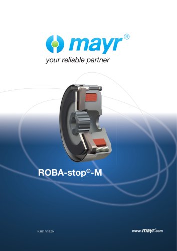 ROBA-stop®-M
24 Pages