
- Catalogs
- Chr. Mayr GmbH + Co. KG
- ROBA-stop®-M


ROBA-stop®-M

ROBA-stop®-M
- Available in sizes 2 to 1000, with braking torques from 0.7 to 1400 Nm for standard brakes and 4 to 1800 Nm for holding brakes.
- Shaft diameters range from Ø 8 to 90 mm.
- Standard design includes friction disks and flange plates, with IP66 protection.
- Electrical power requirements vary, with standard voltages of 24, 104, 180, and 207 V.
- Spring-applied mechanism ensures braking when de-energized; electromagnetic activation releases the brake.
- Brakes engage during power failures or emergency stops.
- Ensure shaft end eccentricity does not exceed 0.2 mm and maintain positional tolerance for threaded holes.
- Follow procedures for mounting the hub, rotor, and optional hand release mechanisms.
- Use original screws and adhere to specified tightening torques.
- Brakes are largely maintenance-free, but rotor wear should be monitored and replaced if necessary.
- Regular inspection of release voltage and rotor thickness is recommended.
- ATEX design available for explosive environments, and UL approval can be requested.
- Torque adjustments possible through different spring configurations.
Catalog excerpts

your reliable partner
Open the catalog to page 1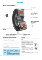
_ your reliable partner . Easy installation Class of insulation F; 100 % duty cycle Short switching times Different torque variants due to variable equipment Long service lifetime Low wear Minimum torsional backlash due to accurate toothing Certain ROBA-stop®-M brakes can be used for safety-relevant applications acc. ISO 13849-1 (for Permitted Types, see page 29). For information on the safety parameters, please contact mayr®power transmission. Advantages for Your Applications □ Easy installation □ Brake outer diameter completely enclosed (higher protection can easily be realised) □ Magnetic...
Open the catalog to page 2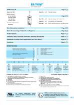
_ your reliable partner _ Braking torques (Standard brake) (Holding brake) Permitted shaft diameter Type 891._ _1.0 Standard design Type 891._ _2.0 Standard design with friction disk Type 891._ _4.1 IP66 design with flange plate Type 891._ _4.2 Tacho attachment design with flange plate Short Description Installation Page 6 P> Brake Dimensioning, Friction-Power Diagrams Page 8 ^ Further Options Page 11 ^ Switching Times, Electrical Connection, Electrical Accessories Page 15 ^ Guidelines on safety-critical applications (acc. ISO 13849-1) Page 20 ^ Order Number Nominal torque holding brake 100%...
Open the catalog to page 3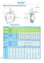
_ your reliable partner _
Open the catalog to page 4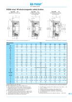
your reliable partner Standard with friction disk Type 891._ _4.1 Enclosed design (IP66) with flange plate L Tacho attachment design with flange plate L * Outer diameter friction disk: Free size; outer diameter flange plate: -0.2 Permitted voltage tolerance acc. DIN IEC 60038 (±10 %). 1) Other adjustments, see Table 3, page 7 and type key page 3. 1.1) Braking torque tolerance = +40 %/-20 % (friction lining pairing conditioning necessary, see Operational Instructions B.8.1._). 1.2) Minimum bore not permitted for Type 891._8_._ 2) The respective maximum bores are to be seen in relation to the corresponding...
Open the catalog to page 5
your reliable partner Installation Conditions □ The eccentricity of the shaft end in relation to the mounting pitch circle must not exceed 0.2 mm. □ The positional tolerance of the threaded holes for the cap screws (Item 8, Fig. 2) must not exceed 0.2 mm. □ The axial run-out deviation of the screw-on surface to the shaft must not exceed the permitted axial run-out tolerance acc. DIN 42955 N. Larger deviations can lead to a drop in torque, to continuous grinding of the rotor and to overheating. 1. Mount the hub (1) onto the shaft and secure it axially (e.g. using a locking ring). - Recommended...
Open the catalog to page 6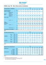
_ your reliable partner _ Brake operation only possible with overexcitation. The braking torque (switching torque) is the torque effective in the shaft train of a slipping brake with a sliding speed of 1 m/s in relation to the mean friction radius (acc. VDE 0580/07.2000).
Open the catalog to page 7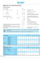
_ your reliable partner . 2. Inspection of thermic load J x n2 M2 The permitted friction work (switching work) Qr zul per braking for the specified switching frequency can be taken from the Friction-Power Diagrams (page 9). If the friction work (switching work) per braking is known, the max. switching frequency can also be taken from the friction-power diagrams (page 9). Mass moment of inertia Safety factor Required braking torque Load torque * sign in brackets (-) is valid if load is braked during downward movement Nominal torque (Technical Data page 4) Please observe the braking torque tolerance!...
Open the catalog to page 8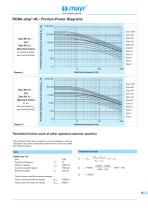
_ your reliable partner . Type 891.01_._ andType 891.21_._ (Standard brake) at reference speed (see Technical Data) Type 891.01_._ andType 891.21_._ (Standard brake) for the Size 1000 Size 500 Size 250 Size 150 Size 100 Size 60 Size 32 Size 16 Size 8 Size 4 Size 2 Size 1000 Size 500 Size 250 Size 150 Size 100 Size 60 Size 32 Size 16 Size 8 Size 4 Size 2 Permitted friction work at other speeds (customer specific) The permitted friction work at specific customer speeds can also be calculated using linear interpolation between the maximum speed and reference speed. Calculation Example Switching...
Open the catalog to page 9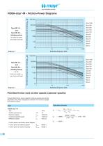
_ your reliable partner . Type 891.10_._ andType 891.50_._ (Holding brake) at reference speed (see Technical Data) Size 1000 Size 500 Size 250 Size 150 Size 100 Size 60 Size 32 Size 16 Size 8 Size 4 Size 2 Type 891.10_._ andType 891.50_._ (Holding brake) for the Size 1000 Size 500 Size 250 Size 150 Size 100 Size 60 Size 32 Size 16 Size 8 Size 4 Size 2 Permitted friction work at other speeds (customer specific) The permitted friction work at specific customer speeds can also be calculated using linear interpolation between the maximum speed and reference speed. Calculation Example Reference speed...
Open the catalog to page 10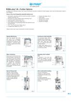
your reliable partner ROBA-stop®-M - Further Options In addition to the standard brakes, mayr® power transmission provides this catalogue. • Microswitch / proximity switch for switching condition indication (release monitoring), Fig. 1 • Microswitch for wear indication (wear monitoring), Fig. 2 • Customer-specific flange plate, Fig. 3 • IP65 design for continuous shafts, Fig. 4 • Noise damping (O-ring damping between the toothed hub and the rotor), Fig. 5 • Lockable hand release, Fig. 7a/7b Please contact mayr® power transmission for further information. a multitude of further designs, which...
Open the catalog to page 11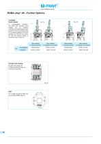
your reliable partner ROBA-stop®-M – Further Options Lockable hand release In de-energised condition, the brake with lockable hand release can be released manually. By deflecting the hand release rod (1), the armature disk (3) is pushed against the thrust springs (4) onto the coil carrier (2) and the braking torque is removed, Figs. 7a and 7b. Hand release in starting position Hand release in engagement position Shaft braked Shaft runs free Hand release in starting position Hand release in engagement position Shaft braked Shaft runs free Coil energised Shaft runs free Shaft runs free Double rotor...
Open the catalog to page 12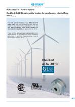
your reliable partner ROBA-stop®-M – Further Options Certified Cold Climate safety brakes for wind power plants (Type 891.4_ _._) The Cold Climate Version of our ROBA-stop®-M safety brake sets new standards for pitch and yaw brakes in low-temperature applications. It is the only electromagnetic safety brake certified by Germanischer Lloyd (GL) for applications to -40 °C. These certified pitch and yaw safety brakes work reliably even in the most arduous climatic conditions and ensure the operation of your systems – even at temperatures of minus 40 °C.
Open the catalog to page 13All Chr. Mayr GmbH + Co. KG catalogs and brochures
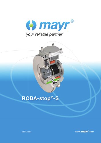 ROBA-stop® S
12 Pages