


EAS®-HT
1 /28Pages
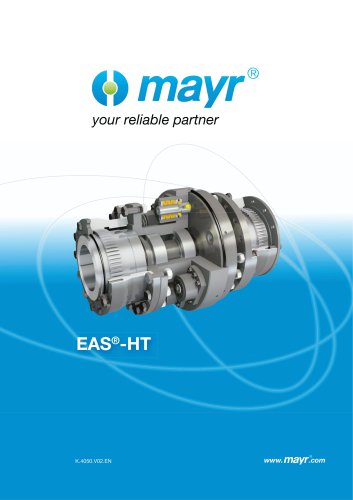
EAS®-HT
1 /28Pages
Catalog excerpts
your reliable partner
Open the catalog to page 1
Always in use EAS®-HT torque limiters for heavy load applications prolong the availability of your production systems. They increase your profit, prevent damage caused by overload damages and save costs. EAS®-HT torque limiters the reliable, non-destructive overload protection • Steplessly adjustable your reliable partner
Open the catalog to page 2
Tested safety For more than 40 years, we have been dimensioning, developing and manufacturing torque limiters for heavy load applications. You can rely on the tested reliability and safety of our heavy load clutch. Experts, not experiments as safety does not allow for compromises
Open the catalog to page 3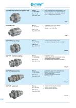
EAS®-HT lastic EAS®-HT flange design EAS®-HT Toothed coupling EAS®-HT backlash-free EAS®-HT lastic bolt <) mayr your reliable partner Direct attachment of the drive element on the bearing-supported, output-side clutch flange. The bearing is able to absorb high additional forces in axial and radial directions. Double shaft design with a flexible, positive locking coupling Absorbs impact-type loads Torque: • Compact, ready-to-install module 7.5 to 440 kNm • Can easily be integrated into the drive line Double shaft design Toothed coupling with crowned teeth cutting High misalignment compensation...
Open the catalog to page 4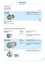
your reliable partner EAS®-HT Options Customer-specific designs Low temperature design Alternative shaft connections Torque limiting or force limiting elements Installation into two flanges located towards one another Integration into existing constructions possible Technical Explanations Page 23 General Misalignment compensation capability Reliable overload protection at high speeds For more information as well as detailed Technical Data and Dimensions, please see our product catalogue EAS®-HSC/ EAS®-HSE. Extruder clutches EAS®-dutytorque Torque: Protect extruder screwsfrom expensive damage...
Open the catalog to page 5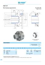
_your reliable partner _ Short bearing-supported hub Type 4050._0400 , Sizes 7 to 10 Order Number 1) Position of the keyway to the tapped hole “s” in the thrust piece is not defined. Defined position available on request. AAA Bores11 Bore Torque adjustment value
Open the catalog to page 6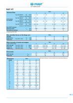
o mayr your reliable partner Technical Data Max. permitted forces on the flange connection Mass moments of inertia and weights We reserve the right to make dimensional and constructional alterations.
Open the catalog to page 7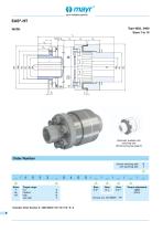
<) mayr your reliable partner Order Number Sizes Torque range A A A A Bore Bore Bore Torque adjustment
Open the catalog to page 8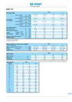
_your reliable partner
Open the catalog to page 9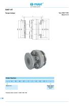
_your reliable partner flange design Example: Order number 5 / 4060.71400 / 200
Open the catalog to page 10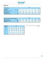
_your reliable partner We reserve the right to make dimensional and constructional
Open the catalog to page 11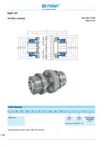
_your reliable partner _ Toothed coupling TyPe 4061 -71400 Sizes 0 to 6 AAA Bore Bore Torque adjust-
Open the catalog to page 12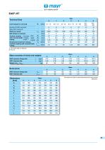
_your reliable partner
Open the catalog to page 13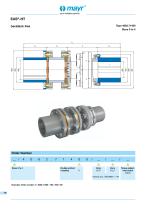
_your reliable partner _ backlash-free Type 4062.71400 Sizes 0 to 4 AAA Bore Bore Torque adjust-
Open the catalog to page 14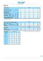
_your reliable partner
Open the catalog to page 15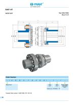
_your reliable partner _ lastic bolt Type 4063.70400 Sizes 4 to 6
Open the catalog to page 16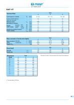
_your reliable partner
Open the catalog to page 17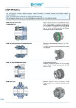
your reliable partner For the EAS®-HT clutches, designs specially created according to customer requests and different variants are also available. EAS®-HT clutches can be combined with additional attachment parts. We are happy to advise you on the dimensioning and configuration of your optimum design. EAS®-HT with automatic re-engagement After overload occurrence, the EAS®-HT torque limiter is disengaged. It is possible to engage the EAS®-HT torque limiter via remote control by means of automatic re-engagement. Re-engagement can be carried out pneumatically, hydraulically, electromechanically...
Open the catalog to page 18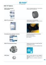
o mayr your reliable partner EAS®-HT with integrated drive elements EAS®-HT, integrated attachment of sprocket and toothed wheels, V-belt disks etc. EAS®-HT for roller gears Highest torques at lowest diameters. The alternative to hydraulic clamping sets and shear pins in rolling mills. Frictionally-locking shaft-hub connection Frictionally-locking shaft-hub connections: • External shrink disk hub EAS®-HT low temperature design ATEX design Reliable overload protection in case of very low temperatures to -48 °C. (Please contact the manufacturer separately for this). EAS®-HT torque limiters are...
Open the catalog to page 19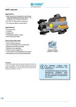
_your reliable partner EAS®-element Application □ EAS®-elements for installation in two bearing-supported flanges facing each other or for integration into existing constructions □ As EAS®-HT torque limiter component □ Underground mining / mining □ Safe overload protection □ Can be used flexibly and in modular form □ Maximum performance density □ Release forces adjustable □ Easy and quick engagement Rustproof design □ Large number of disengagement procedures available on request □ Re-greasing via the cone lubricating nipple The catalogue contains basic information on pre-selection and dimensioning....
Open the catalog to page 20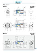
your reliable partner
Open the catalog to page 21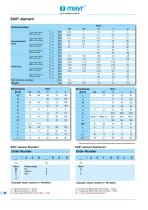
_your reliable partner Sizes Torque range 02 low 4 Example: Order number 0 / 440.504.0Sizes 0 Example: Order number 0 / 441.604.0 4) Fixing screw DIN EN ISO 4762 10.9 MA = 19 Nm
Open the catalog to page 22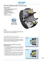
o mayr _your reliable partner _ □ Easy repeat operation start-up □ Long service lifetime Design All clutch parts are made of steel. EAS®-HT torque limiters basic components have a zinc-phosphated surface which provides a basic corrosion protection for further surface treatments. Clutch types 4050, 4060 are also suitable for oil running. The limit torque for overload on the clutch can be adjusted by changing the cup spring pre-tension of each overload element. The EAS®-HT torque limiters can be set to the required limit torque for overload at the place of manufacture. Subsequent torque changes...
Open the catalog to page 23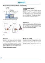
_your reliable partner Processes for torque switch-off on overload: On overload, the hub part 1 and the output flange 2 begin to turn against each other. The bolts 3.1 in the overload elements are pressed via the control segments 3.4 against the force of the cup springs 3.6 from the thrust pieces 3.2. The control segments 3.4 travel radially outwards over the bolt 3.1 switching edge and hold the bolts 3.1 in a disengaged position (see Fig. 2). The positive locking connection of the hub part 1 and the output flange 2 is nullified. The originally coupled masses can slow down freely. The drive is...
Open the catalog to page 24All Chr. Mayr GmbH + Co. KG catalogs and brochures
 EAS®-Sp EAS®-Sm/Zr
24 Pages
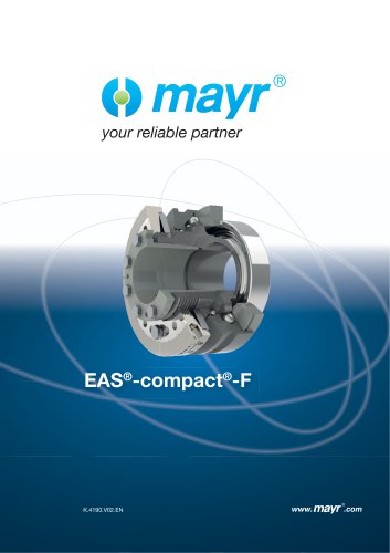 EAS®-compact®-F
32 Pages
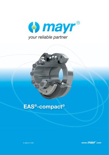 EAS®-compact®
40 Pages
 tendo®-PM
44 Pages
 ROBATIC®, ROBA-quick® ROBA®-takt
60 Pages
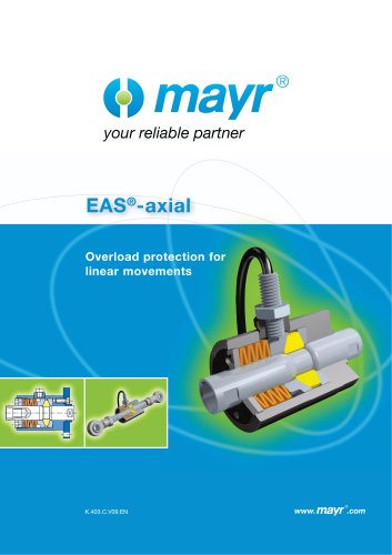 EAS®-axial
24 Pages
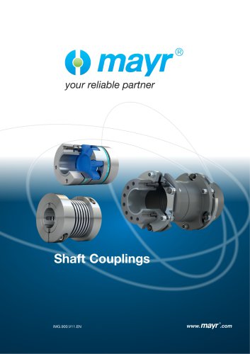 Shaft Couplings
20 Pages
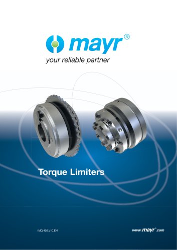 Torque Limiters
28 Pages
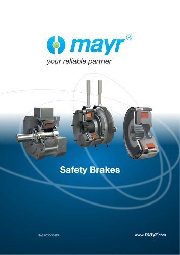 Safety Brakes
24 Pages
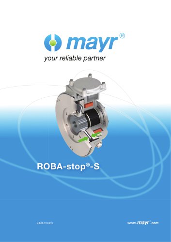 ROBA-stop® S
12 Pages
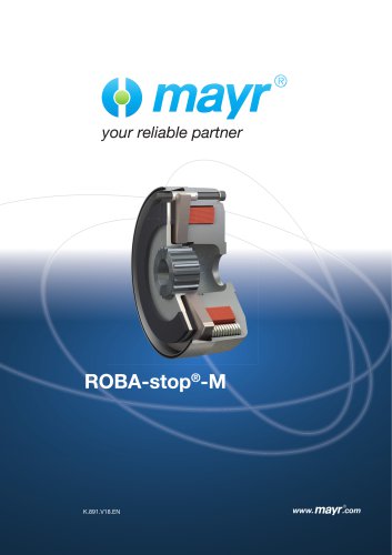 ROBA-stop®-M
24 Pages