Plunger Pumps
1 /20Pages

Plunger Pumps
1 /20Pages
Catalog excerpts

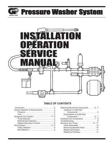
RR Series Pumps RR Series Pumps Operating Instructions and Parts Manual Operating Instructions and Parts Manual Plunger Pumps Please read and save these instructions. Read carefully before attempting to assemble, install, operate or maintain the product described. Protect yourself and others by observing all safety information. Failure to comply with instructions could result in personal injury and/or property damage! Retain instructions for future reference. Description Plunger Pumps are designed for a wide variety of high pressure washing applications. They are constructed with die-cast bodies and feature a brass head. Internal components include special thick solid ceramic plungers for long life and durability. Precision cast cooling fins are anodized for maximum heat dissipation. Oversized needle bearings on the drive side, and ball on the non-drive side together with the precision supports assure positive alignment and centering in relation to the crankcase. Valve cages of special designed Ultra-Form provide positive seating and extended life. Ball bearings on both sides of solid shaft drive pumps. One-piece connecting rods are special alloy aluminum, oversized for strength and load disbursement. These pumps are designed for, belt drive, or coupling drive systems driven by electric motor or gasoline driven systems, electric motor direct drive systems, and gasoline engine direct drive systems. RR 1450 rpm N Version - Solid Shaft Model Max GPM Max PSI RR15.20N 4.0 2900 RR18.16N 4.8 2320 RCA 1750 rpm N Version - Solid Shaft Model Max GPM Max PSI RRA3.5G30N 3.5 3000 RRA4G30N 4.0 3000 RRA5.5G30N 5.5 3000 NORTH AMERICA First Performance Pumps HighChoice When Quality Matter
Open the catalog to page 1
Operating Instructions and Parts Manual Plunger Pumps RR/RRA N version Solid shaft pump / ø 24 mm E version + F17 Hollow shaft pump ø 1-1/8” D version + F24 Hollow shaft pump ø 1” NORTH AMERICA First Choice When Qual
Open the catalog to page 2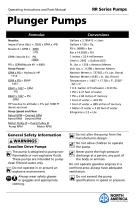
Operating Instructions and Parts Manual Plunger Pumps Formulas Nozzles: Impact Force (lbs.) = .0526 x GPM x √PSI Nozzle # = GPM x 4000 √ PSI GPM= Nozzle # x PSI = (GPM/Nozzle #)2 x 4000 Horse Power: GPM x PSI = Hydraulic HP 1714 GPM x PSI = EBHP 1457 EBHP x 1457 = GPM PSI EBHP x 1457 = PSI GPM HP loss due to altitude = 3% per 1000 FT above sea level Pump Speed and Flow: Rated GPM = Desired GPM Rated RPM Desired RPM Conversions Gallons x 3.785412 = Liters Gallons x 128 = Oz. PSI x .06896 = Bar Bar x 14.5038 = PSI 1 inches = 25.4 millimeters Liters x .2642 = Gallons (US) Ft. Lbs. x 1.356 = Newton...
Open the catalog to page 3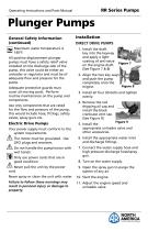
Operating Instructions and Parts Manual Plunger Pumps General Safety Information (continued) Maximum water temperature is 140°F. All positive displacement plunger pumps must have a safety relief valve installed on the discharge side of the pump, this valve could be either an unloader or regulator and must be of adequate flow and pressure for the pump. Adequate protective guards must cover all moving parts. Perform routine maintenance on the pump and components. Use only components that are rated for the flow and pressure of the pump, this would include hose, fittings, safety valves, spray guns...
Open the catalog to page 4
Operating Instructions and Parts Manual Plunger Pumps Installation (continued) BELT DRIVE SYSTEMS 1. Mount the pump securely to the base plate. (See Figure 10) For new installation a Figure 10 mounting rail kit is required, refer to parts breakdown. 2. Install the pump pulley on the crankshaft. It should be as far onto the shaft as possible. 3. Align the pulleys so they are in line. (See Figure 11) 4. Use a belt tension gauge to assure proper tension (too much tension can cause bearing failure or damage the belts as well as cause other problems). (See Figure 12) 5. Installation complete. Maintenance...
Open the catalog to page 5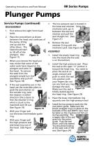
Operating Instructions and Parts Manual Plunger Pumps Service Pumps (continued) DISASSEMBLY 1. First remove the eight 5mm head bolts. 2. Place the screwdrivers as shown between the head and crankcase of the pump, lifting one up and the other down. The head should start to lift off of the plungers. (See Figure 17 Figure 17) 3. When you remove the head you may notice that some of the water seals have stayed on the plungers and some in the head. To remove the seals from the plungers simple turn the assemblies and pull off. Figure 18 (See Figure 18) 4. If the seal assemblies are in the head use the...
Open the catalog to page 6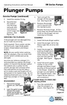
Operating Instructions and Parts Manual Plunger Pumps Service Pumps (continued) 5. Install the retainer O-ring. 6. Squarely seat the retainer into the head and push with even pressure until it snaps into Figure 25 position. (See Figure 25) 3. Twist and pull the plunger off the plunger rod. (See Figure 28) 4. Remove the plunger rod O-ring seal with the mechanics pick. 5. Remove the brass slinger. At this point clean any thread locker that is left on the plunger rod and retaining nut threads. If the plungers are not damaged they do not need any servicing. 1. Install the brass slinger washer. Tools...
Open the catalog to page 7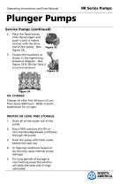
Operating Instructions and Parts Manual Plunger Pumps Service Pumps (continued) 2. Place the head evenly onto the plungers and push it until it makes contact with the drive end of the pump. (See Figure 32) 3. Torque the head bolt as shown in the tightening sequence diagram. (See Figure 33 & 34) (See Table D or parts breakdown) Figure 33 OIL CHANGE Change oil after first 50 hours of use. Then every 500 hours. Refer to parts breakdown for oil type. WINTER OR LONG TIME STORAGE 1. Drain all of the water out of the pump. 2. Run a 50% solution of a RV or non-toxic/biodegradable antifreeze through the...
Open the catalog to page 8
Operating Instructions and Parts Manual Plunger Pumps Notes NORTH AMERICA First Choice When Quality Matters
Open the catalog to page 9
Operating Instructions and Parts Manual Plunger Pumps Troubleshooting Symptom Possible Cause(s) Oil leak between crankcase and pumping section Frequent or premature failure of the packing Corrective Action Replace crankcase piston rod seals Cracked, damaged or worn plunger Replace plungers Overpressure to inlet manifold Reduce inlet pressure Material in the fluid being pumped Install proper filtration on pump inlet plumbing Excessive pressure and/or temperature of fluid being pumped Check pressures and fluid inlet temperature; be sure they are within specified range Do not run pump without water...
Open the catalog to page 10All CaviDyne catalogs and brochures
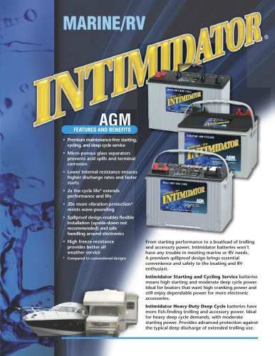 AGMIntimidator Battery
2 Pages
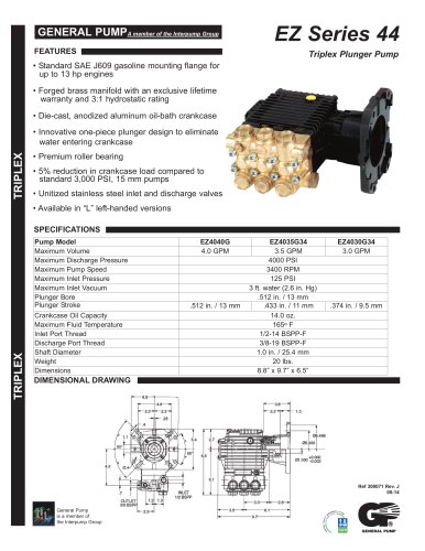 T RIP L E X
2 Pages
 CH260-CH440
100 Pages
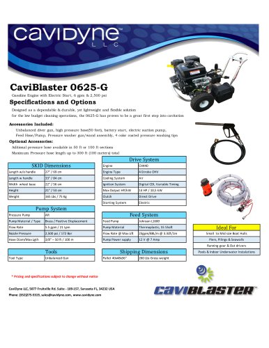 CaviBlaster 0625-G
1 Page
 CaviBlaster 1030-ROV
1 Page