INSTALLATION OPERATION SERVICE MANUAL
1 /12Pages
INSTALLATION OPERATION SERVICE MANUAL
1 /12Pages
Catalog excerpts
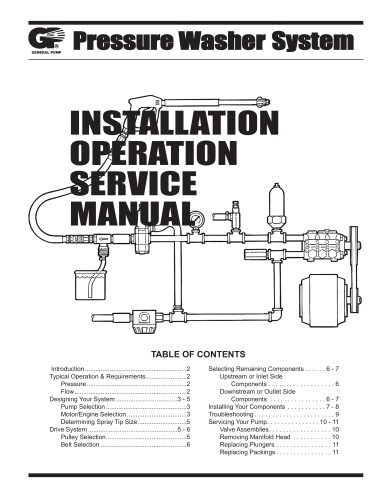
Pressure Washer System INSTALLATION OPERATION SERVICE MANUAL Selecting Remaining Components . . . . . . 6 - 7 Upstream or Inlet Side Components . . . . . . . . . . . . . . . . . . . 6 Downstream or Outlet Side Components . . . . . . . . . . . . . . . . 6 - 7 Installing Your Components . . . . . . . . . . . 7 - 8 Troubleshooting . . . . . . . . . . . . . . . . . . . . . . . 9 Servicing Your Pump. . . . . . . . . . . . . . . 10 - 11 Valve Assemblies. . . . . . . . . . . . . . . . . . 10 Removing Manifold Head . . . . . . . . . . . 10 Replacing Plungers . . . . . . . . . . . . . . . . 11 Replacing Packings . . . . . . . . . . . . . . . . 11
Open the catalog to page 1
or closed, therefore a device is needed to control the direction of flow, either allowing the flow to go through the open spray gun, or redirecting (by-passing) the flow back to the inbound side of the pump when the spray gun is closed. Without an unloading or regulating valve, dangerously high pressures will be produced when the spray gun is closed because the water being forced out of the pump has no place to go. Serious bodily injury or property damage could be caused by failure to properly utilize an appropriate unloader or regulator valve in your pressure washer system. As a safety device,...
Open the catalog to page 2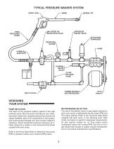
TYPICAL PRESSURE WASHER SYSTEM UNLOADER OR REGULATOR VALVE HIGH PRESSURE HOSE PRESSURE RELIEF VALVE PRESSURE GAUGE PULSATION DAMPENER CHEMICAL INJECTOR THERMAL RELIEF VALVE FLUID BY-PASS HOSE POWER SOURCE (MOTOR/ENGINE) INLET FILTER DESIGNING YOUR SYSTEM Drive System MOTOR/ENGINE SELECTION The size of the electric motor or gas engine required to drive your pump is determined by the pump GPM and PSI output desired. Refer to the Technical Data Sheet supplied with each pump, or the following chart. Both charts are based on electric horsepower requirements; for gas engines multiply by 1.8. Gas engine...
Open the catalog to page 3
ELECTRIC MOTOR HORSEPOWER REQUIRED TO DRIVE A PUMP OUTPUT VOLUME (GPM) AT VARIOUS PRESSURES (PSI) Check with your motor supplier for technicla information. SPRAY TIP SELECTION CHART A gasoline engine should be sized 1.8 times the electric horsepower requirement. Always select a motor/engine with a horsepower rating above the minimum requirements shown above. Example: 5.0 GPM - 1250 PSI is 4.40 minimum electric horsepower requirement, use a 5 horsepower electric motor. If you wish to direct drive your pump from an electric motor, you may want to use a “C” face motor. A commonly used standard for...
Open the catalog to page 4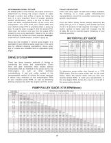
DETERMINING SPRAY TIP SIZE As stated earlier in this manual, the output pressure is determined by forcing the output volume of water through a certain size orifice or spray tip. Spray tip size is a very important factor of proper pressure washer performance, using a tip that is sized too small will allow overpressurization of the pump and components. You must know your output GPM and your desired output PSI to properly select a spray tip size. To use the chart on page 4, find the desired PSI, read down the column until you find the output GPM closest to your pump application. Read to the far...
Open the catalog to page 5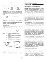
If your motor/engine will be operated at a speed other than 1725 RPM, the pump pulley diameter can be calculated using the following formula: RPM Ration Motor Pulley Diameter Pump Pulley Diameter Example: Using a 1200 RPM motor, and a pump that you want to turn at 850 RPM for your desired GPM output, and you have chosen a 4-1/2” diameter motor pulley. 1200 850 1.412 x 4.5 = 6.39 actual pump pulley diameter. There may not be a pulley available in the exact size as calculated. Simply use the closest one. BELT SELECTION Be sure to use the same section belts (A, B or C) as the pulleys were sized...
Open the catalog to page 6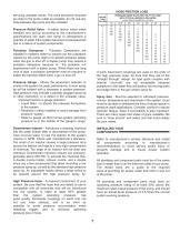
servicing unloader valves. The valve should be mounted as close to the pump outlet as possible; do not use any hose between the pump and the unloader. WATER FLOW GAL/MIN Pressure Relief Valve - A safety device which when installed and set-up according to the manufacturer’s specifications will open and dump to atmosphere a quantity of water if the system becomes overpressurized due to a failure of system components. Pulsation Dampener - Pulsation Dampeners are installed in systems either to smooth out the pulsations caused by the pump itself or to absorb pressure spikes when the gun is shut off....
Open the catalog to page 7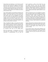
Avoid bends and restrictions in the inlet and outlet plumbing. They force the motor.engine to work harder to drive the pump (reduction of efficiency) and create turbulence in the water flow which can cause cavitation on the inlet side and premature wear in the pump and in the outlet plumbing. Bends and restrictions will cause a reduction in outlet pressure and increased amp draws with and electric motor. pump crankcase or pulley. A gas engine has only one rotation direction, which may vary between manufacturers. Be sure you know the rotation direction before you begin assembly. Most electric...
Open the catalog to page 8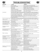
PROBLEM Pulsation Faulty pulsation damper. Check precharge; if low, rechargeit or install a new one. Valve stuck open. Check all valves, remove foreign matter. Worn nozzle. Replace nozzle, of proper size. Belt slippage. Tighten or replace; use correct belt. Air leak in inlet plumbing. Low pressure Relief valve stuck; partially plugged or improperly adjusted valve seat worn. Worn packing. Abrasives in pumped fluid or severe cavitation. Inadequate water. Worn inlet, discharge valve blocked or dirty. Water leakage from under manifold. Slight leakage. Oil leak between crankcase and pumping section....
Open the catalog to page 9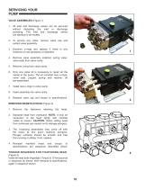
SERVICING YOUR PUMP VALVE ASSEMBLIES (Figure 1) 1. All inlet and discharge valves can be serviced without disrupting the inlet or discharge plumbing. The inlet and discharge valves are identical in all models. 2. To service any valve, remove valve cap and extract valve assembly. 3. Examine o-rings and replace if there is any evidence of cuts abrasions or distortion. 4. Remove valve assembly (retainer, spring valve, valve seat) from valve cavity. 5. Remove o-ring from valve cavity. 6. Only one valve kit is necessary to repair all the valves in the pump. The kit included new o-rings, valve seat,...
Open the catalog to page 10All CaviDyne catalogs and brochures
 AGMIntimidator Battery
2 Pages
 Plunger Pumps
20 Pages
 T RIP L E X
2 Pages
 CH260-CH440
100 Pages
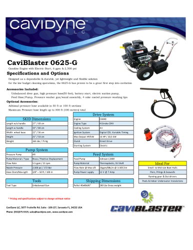 CaviBlaster 0625-G
1 Page
 CaviBlaster 1030-ROV
1 Page


