Catalog excerpts

BALMAR 97-SERIES ALTERNATOR DATA SHEET REVISED 08/24/10 Balmar’s 97-Series, extra-large case alternators deliver the size and charging output required to support battery banks of up to 750 amp hours at 12 volts or 500 amp hours at 24 volts. These 12-volt and 24-volt alternators are engineered for use with external multistage voltage regulation, making it possible to tailor charging voltage to maximize safety and efficiency when replenishing a wide variety of battery types. A robust J180 saddle-style dual foot mounting configuration is ideal as a replacement for standard J180 mount alternators or for use as a second alternator on custom J180 saddle mount brackets. Isolated grounding termination provides sure continuity to system ground. High amperage diodes and extra-large sealed bearings ensure dependability and long alternator life. Included in the 95-Series alternator family are: 150-amp/12-volt; 165-amp/12-volt; 210-amp/12-volt; and 140-amp/24-volt models. All models meet U.S. Coast Guard Title 33 standards for ignition protection. SPECIFICATIONS ALTERNATOR STYLE: Extra-Large Case REGULATION: External P-type CASE CONSTRUCTION: Cast aluminum FINISH: White powdercoating COOLING: Bi-directional external fan DIODES: 6-positive, 6-negative; 50A/200V MINIMUM REQUIRED BELT CONFIGURATION: Dual 1/2” vee; 8-groove serpentine GROUND TERMINATION: Case independent (isolated) TACH OUTPUT: Unrectified AC stator outputs (3) BEARINGS: Sealed ball bearing. Heavy duty radial (front). Heavy duty needle (rear) TENSIONING ARM: 180˚ offset from mounting foot AVAILABLE OUTPUTS: 165A/12V, 210A/12V, 140A/24V MOUNTING STYLE: 4” I.D. saddle mount (J180-style). IGNITION PROTECTION STANDARDS: USCG TITLE 33, CE, J1171, SAE 8846.
Open the catalog to page 1
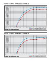
OUTPUT CURVES - 160A (12-VOLT MODELS) R PM S O COLD (122°F) ALTERNATOR AMPERAGE OUTPUT 140A/24V ALTERNATORS O H0T (190°F) ALTERNATOR AMPERAGE OUTPUT
Open the catalog to page 2
ITEM DESCRIPTION Case Diameter Bolt-to-Bolt Center Overall Height Overall Length Sheave center to front foot Front Foot Width Inside front to rear foot Field Terminal Rear foot (including spacer) Mounting foot aft of alternator Sheave center to front foot Front Foot Width Positive Output Ground Terminal ADDITIONAL ALTERNATOR MEASUREMENTS Dimension Mounting Foot Bore Terminal Connection Locations 1 Positive Output Terminal Ground Terminal Field Input Terminal Stator/Tach Output Terminal PLEASE NOTE: Measurements provided are believed to be correct at the time of publication. Diagrams shown...
Open the catalog to page 3All Balmar catalogs and brochures
-
2016 Balmar Catalog
36 Pages
-
95-series
4 Pages
-
94 / 94LY-series
4 Pages
-
AT-series
4 Pages


