
- Catalogs
- APLISENS S.A.
- APR-2000ALW

APR-2000ALW

APR-2000ALW
- Output Signal: 4...20 mA with HART 5/7 protocol.
- Accuracy: 0.1%.
- Safety Certification: SIL2/SIL3.
- Certificates: ATEX, IECEx, FM, INMETRO, UKCA, KCS, DNV, BV.
- Protection: IP66/IP67.
- Pressure difference measurement in gases, vapors, and liquids.
- Hydrostatic level, density, and phase boundary measurement.
- Suitable for environments with pressure surges and overloads up to 40 bar.
- Configurable parameters: pressure units, range start/end points, time constant.
- Communication via KAP-03 communicator or HART/USB converter.
- Calibration involves setting measurement range and compensating for hydrostatic pressure.
- Use identical diaphragm seals for optimal results.
- Consider ambient temperature effects and select appropriate seal diaphragms.
- Select manometric fluid based on medium properties and temperature range.
- Nominal ranges: -160...160 mbar to -1.6...16 bar.
- Static pressure limit: 40 bar.
- Level measurement: Configure transmitter with tank empty and adjust for manometric fluid pressure.
- Density measurement: Calculate range start based on diaphragm seal spacing and fluid density.
- Operating temperature: -25 to 85°C (varies by version).
- Medium temperature range specified in diaphragm seal sheet.
1. Calculate the end of the measurement range using the formula: H[mm] × (Xmax – Xoil). Example: 3000 × (1.2 – 1.068) = 396 mm H2O.
2. Set the zero point of the transmitter with diaphragm seals at the same level.
3. Install the transmitter in its working position and make electrical connections, allowing for HART communication.
4. Use the KAP-03 communicator to configure the transmitter, selecting the 'Reranging' procedure and setting measurement units to mm H2O at 4°C. Enter start (-1404) and end (396) range values.
To measure the phase boundary height between liquids of different densities, calculate the average density of the medium between the seals. Example: For an APR-2000/ALW transmitter measuring between densities of 0.7 g/cm³ and 1.0 g/cm³ with a seal spacing of 1600 mm, calculate the start and end points of the range.
- Start: 1600 mm × (0.7 – 1.068) = -588.8 mm H2O.
- End: -588.8 mm H2O + (1.0 – 0.7) × 1000 mm = -288.8 mm H2O.
- Adjust transmitter settings based on laboratory density measurements, especially in high flow velocity conditions.
- Increasing diaphragm seal spacing can improve measurement accuracy.
- Ensure pressure difference at the transmitter is within the basic range.
- Maximum seal spacing depends on the transmitter's range and liquid density boundaries.
For an APR-2000ALW/-10...10 kPa transmitter measuring liquid density between 0.6 and 1.2 g/cm³ using AK-20 silicone oil (density 0.945 g/cm³):
- Lower boundary: -10 kPa = -1020 mm H2O, resulting in a maximum spacing of 2957 mm.
- Upper boundary: +10 kPa = 1020 mm H2O, resulting in a maximum spacing of 4000 mm.
Both conditions are satisfied when seal spacing is not more than 2957 mm.
Catalog excerpts

SMART DIFFERENTIAL PRESSURE TRANSMITTER WITH TWO DIAPHRAGM SEALS MODEL APR-2000ALW (former APR-2200ALW) ü ü ü ü ü ü ü ü 4...20 mA output signal + HART 5 / HART 7 protocol /SIL3 Accuracy 0,1% SIL2 version y Safety version SIL2/SIL3 safet Intrinsic safety certificate ATEX, IECEx, FM (USA, Canada), INMETRO, UKCA, KCS Explosion proof certificate ATEX, IECEx, FM (USA, Canada), INMETRO, UKCA, KCS Marine certificate – DNV, BV Fully welded sensor guarantees tightness of oil system for many years Ability to configure measuring range locally Transmitter with two remote diaphragm seals Differential pressure transmitter Coiled excess capillary Capillary outlet in the axis of the diaphragm seal Diaphragm seals Example of a filter loss measurement Recommendations The version of the transmitter with two remote diaphragm seals is recommended for the measurement of pressure differences when the hydrostatic pressure of the manometric fluid in the capillaries (which depends on the vertical spacing of the seals) is significantly less than the measuring range of the transmitter. The best metrological results are obtained when the applied capillaries are identical, as short as possible, and terminated with identical seals. At such a configuration additional temperature errors, related to the remote sealing, affect both of the measurement chambers of the differential pressure transmitter in the same way, and thus cancel each other out.
Open the catalog to page 1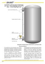
Transmitter with two types of diaphragm seal: one – direct diaphragm seal and the other – remote diaphragm seal Upper remote diaphragm seal Capillary fastened to a guide Coiled excess of the capillary Differential pressure transmitter Lower direct seal Example of measurement of the level in a pressure tank Recommendations The transmitter with a direct diaphragm seal (connected to the positive measurement chamber) and a remote diaphragm seal (connected to the negative chamber) is recommended for hydrostatic measurements of: levels, densities, phase boundaries and pressure differences (with differentiated...
Open the catalog to page 2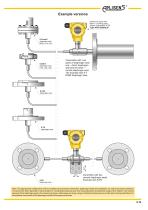
Example versions Aluminium casing with M20×1.5 packing gland Degree of protection IP 66 S-CompK diaphragm seal M20×1.5 or Æ51 S-DIN K diaphragm seal Æ50, Æ65, Æ80 Transmitter with two types of diaphragm seal: one – direct diaphragm seal and the other – remote diaphragm seal. The example with S-T DN80 diaphragm seal. S-ChK diaphragm seal transmitter with two remote diaphragm seals. Example with S-PK Note: The appropriate configuration of the complete set of pressure transmitter, diaphragm seals and capillaries, as well as the proper selection of manometric fluid, depends on several factors, including...
Open the catalog to page 3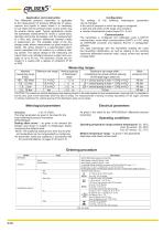
The differential pressure transmitter is applicable to the measurement of pressure differences of: gases, vapours and liquids in cases where it is necessary to use seals and the pressure pulse source points may be several metres apart. Typical applications include the hydrostatic measurement of: levels in closed tanks, densities and phase boundaries, and the measurement of a filter loss, pressure differences between media in pasteurisers etc. The available range of the diaphragm seals allows measurement at great majority of media. The active element is a piezoresistant silicon sensor separated...
Open the catalog to page 4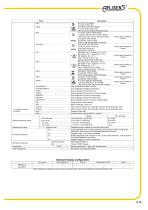
Nominal measuring range Process connections Electrical connection Accessories Other specification Description Ex ia IIC T5/T4 Ga/Gb Ex ia IIIC T105°C Da II 1/2 G Ex ia IIC T5/T4 Ga/Gb II 1 D Ex ia IIIC T105°C Da I M1 Ex ia I Ma (version with SS housing) II 1/2G Ex ia/db IIC T6/T5 Ga/Gb II 1/2D Ex ia/tb IIIC T85°C/T100°C Da/Db Packing gland available on I M2 Exd ia I Mb (version with SS housing) request Ex ia/db IIC T6/T5 Ga/Gb IECEx Ex ia/tb IIIC T105°C Da/Db Ex db ia I Mb (version with SS housing) II 2G Ex db ia IIC T6/T5 Gb II 2D Ex ia tb IIIC T105°C Db Packing gland available on request Ex...
Open the catalog to page 5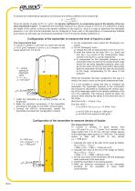
To simplify the mathematical operations we introduce the density coefficient of the medium Xr. Xr = Since the density of water at 4°C is 1 g/cm3, the density coefficient Xr is numerically equal to the density of the medium expressed in g/cm3. To determine the hydrostatic pressure of a column of liquid in mm H2O, it is sufficient to multiply the height of the column h [mm] by the density coefficient of the liquid Xr. Since it is easy to determine the hydrostatic pressure in mm H2O and the transmitter can be configured in those units, in the descriptions of measurement methods given below we will...
Open the catalog to page 6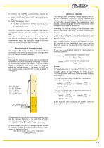
6. Connect the KAP-03 communicator, identify the transmitter and select the “configuration” function. 7. On the configuration menu select “Reranging” procedure. 8. On the “Reranging” menu: a) change the measurement units to mm H2O at 4°C; b) enter the calculated values for the start (–1404) and end (396) of the range. When the transmitter has been configured in this way it is ready to be used to carry out the given measurement task. Note: If it is possible to fill the space between the seals with a liquid whose density corresponds to the start of the measurement range, the start of the range...
Open the catalog to page 7All APLISENS S.A. catalogs and brochures
 PEM-500
4 Pages
 MS-100
1 Page
 MS-100K
1 Page
 PR - G
2 Pages
 APR -2000G
3 Pages
 APR-2000ALW/G
3 Pages
 APM-2
APM-23 Pages
 AS-dP
AS-dP1 Page
 PRE-28.MODBUS
3 Pages
 PRE-28.SMART
3 Pages
 APRE-2000
3 Pages
 APCE-2000
3 Pages
 AS
AS1 Page
 PC-29A and PC-29B
2 Pages
 PCE-28.MODBUS
3 Pages
 PCE-28
3 Pages
 PCE-28.SMART
3 Pages
 APC-2000ALW
5 Pages
 APC-2000ALM
3 Pages
 PEM-1000
4 Pages
 RH
RH3 Pages
 ERH-xx-20
2 Pages
 ERH-11-20
1 Page
 ERH-SMALL
2 Pages