
- Catalogs
- Alphatron Marine
- AlphaHeading Indicator MFM


- Products
- Catalogs
- News & Trends
- Exhibitions
AlphaHeading Indicator MFM
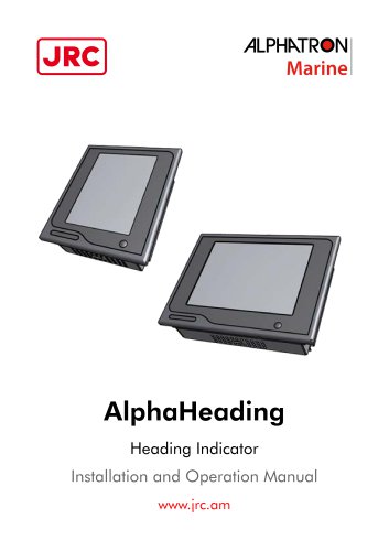
AlphaHeading Indicator MFM
Catalog excerpts
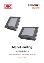
/UPHkTR^N Marine AlphaHeading Heading Indicator Installation and Operation Manual www.|rc.am
Open the catalog to page 1
>ILPHMR«N Marine The Alphatron Marine AlphaLine instrument range was designed for navigation and control of ships and is based on generic hardware and software, allowing for many different applications. • Thoroughly read this instruction manual before installation and operation of the equipment. • We recommend to keep this manual nearby the equipment to ensure ready access to it.
Open the catalog to page 4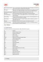
>ILPHMR«NMarine Reverse polarity protection Abbreviations as used in this manual are explained in Table 2: Abbreviations on page 5.
Open the catalog to page 5
>ILPHMR«N Marine The AlphaHeading complies with the applicable standards, norms and regulations:
Open the catalog to page 6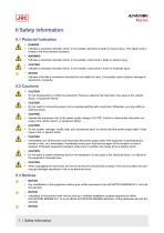
II Safety Information II.1 Pictorial Indication • Indicates a hazardous situation which, if not avoided, will result in death or serious injury. This signal word is limited to the most extreme situations. Indicates a hazardous situation which, if not avoided, could result in death or serious injury. Indicates a hazardous situation which, if not avoided, could result in minor or moderate injury. Indicates information considered important but not related to injury. It is typically used to prevent damage to equipment or property. Do not disassemble or modify the equipment. Failure to observe this...
Open the catalog to page 7
>ILPHMR«N Marine • This product must be installed in accordance with the installation methods described in this manual. Acting otherwise will void the warranty. • This product contains no operator serviceable parts. Service and repair shall only be carried out by personnel trained and certified by ALPHATRON MARINE B.V. • Do not allow the instrument to fall or immerse into water. The equipment can be damaged. • If the instruments are not stored as described, it will void the warranty. • When cleaning the surface, do not use any organic solvent such as thinner or benzine. Otherwise, the paint and...
Open the catalog to page 8
III Introduction Each type in this navigation and control instrument product range consists of a display unit and, if applicable, one or more external remote I/O modules. The following display sizes are available for your AlphaLine instrument: The AlphaHeading is a Type Approved system for showing the ship's Heading information from a standard ship's compass.
Open the catalog to page 9
>ILPHMR«N Marine Installation follows a generic method and is applicable to the complete range of AlphaLine instruments. This chapter describes the installation into a console. • This product must be installed in accordance with the installation methods described in this manual. Acting otherwise will void the warranty. The Location Class/Category of the AlphaLine instrument is: EXPOSED (may be used outside), but only if installed with the optional sealing kit and according the installation instructions as mentioned in Mounting Instrument on page 10. 1.1.1 Supplied Parts The AlphaHeading is supplied...
Open the catalog to page 10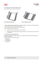
>ILPHMR«NMarine 1.1.4 Fitting Instrument Mounting Frame Prior to fitting the display unit, install the mounting frame. 1. Make a square hole in the (overhead) console. Use the provided template. For dimensions, see Mechanical Drawing MFM on page 54 or Mechanical Drawing MFL on page 55. 2. Push the mounting frame into the hole and attach it with four screws. 3. Push the display unit into the mounting frame. Note The instrument is locked into position by a spring system. Note Use the Overhead Mounting Kit for securing the display unit to an overhead console, to prevent the unit from falling out....
Open the catalog to page 11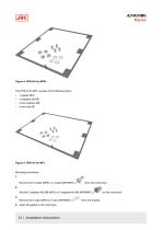
>ILPHMR«NMarine The IP56 Kit for MFL consists of the following items: Mounting instructions: Remove the 2 snaps (MFS) or 4 snaps (MFM/MFL) ( Add the 2 adapters M3-M6 (MFS) or 4 adapters M3-M6 (MFM/MFL) () Remove the 2 clips (MFS) or 4 clips (MFM/MFL) ( ) from the bracket. 4. Apply the gasket to the instrument.
Open the catalog to page 12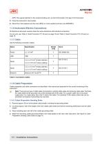
>ILPHMR«NMarine INFO: Pay special attention to the small protruding cam, so that it fits exactly in the gap in the front panel. 5. Place the instrument in the bracket. 6. Mount the 2 lock washers and hex nuts (MFS) or 4 lock washers and hex nuts (MFM/MFL). All AlphaLine instrument versions share the same electronics with identical connections. For pin-outs, see Table 4: Serial Connector P12 (8 pins) on page 18 and Table 5: Serial Connector P19 (12 pins) on page 18. Use the following connection cables: Table 3: Connection Cables Cable preparation and cable connections as described in this manual...
Open the catalog to page 13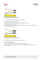
Figure 6: Cable Preparation Sending Cable Sides Note Always check the drawing for the correct shielding of signals. 1.1.8.2 Cable Preparation Receiving Sides 1. Remove approx. 80 mm of the plastic cable sheath, including the grounding shield. 2. Wrap insulating tape over the cable end. 3. Attach the isolated cable end to the metal saddle on the rear of the instrument. See Figure 7: Cable Preparation Receiving Cable Sides on page 14. Figure 7: Cable Preparation Receiving Cable Sides Note Always check the drawing for the correct shielding of signals. 1.1.9 Grounding Instrument To function properly,...
Open the catalog to page 14
Figure 8: Grounding Bolt Note The grounding strap must be as short as possible. If wire is used, use a minimum of 2.5 mm copper wire. See Figure 8: Grounding Bolt on page 15. Note Always check the drawing for the correct shielding of signals. 1.1.10 Instrument Power Supply The AlphaLine instrument has one 24 VDC (nominal) power input. Power consumption is approx. 500 mA. Connect to a power supply > 1 A. Note The power supply input is protected against connecting to the wrong polarity. Note In rush current approximately 4 A.
Open the catalog to page 15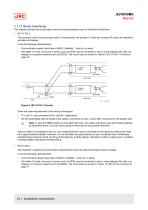
1.1.11 Serial Interfaces This chapter provides extra information about the serial interfaces used in the Marine Electronics. • IEC 61162-1 This standard is the most commonly used. In the standard, the sender (Tx side) and receiver (Rx side) are referred to as talker and listener. It has the following characteristics: • Communication speed: baud rate of 4800, 8 databits, 1 stop bit, no parity. One talker (Tx side, commonly a sensor such as GPS) may be connected to one or more listeners (Rx side, e.g. displays or computer systems such as ECDIS). The circuit looks as shown in Figure 9: IEC 61162-1...
Open the catalog to page 16All Alphatron Marine catalogs and brochures
 AlphaTurn Indicator MFM
57 Pages
 AlphaHeading + Indicator
57 Pages
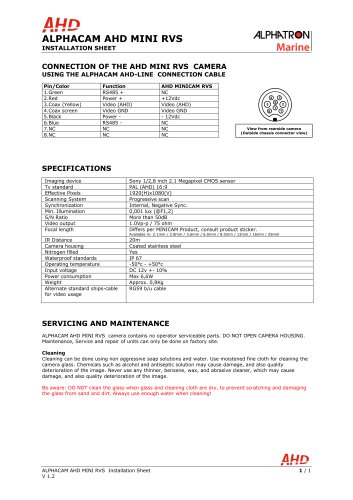 AlphaCam AHD Mini SS
1 Page
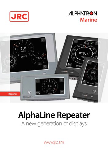 AlphaLine Repeater MFS
20 Pages
Archived catalogs
 AlphaDynaPos
2 Pages
 AlphaDynaPos
1 Page
 AlphaMiniCourse Mk2
9 Pages
 AlphaHeatDetectionSystem
8 Pages
 AlphAtrio pilot MF
2 Pages
 Jax 9B
4 Pages
 Alphawind MF
2 Pages
 AlphaLine Repeater
8 Pages
 Alphaconnect P210
1 Page
 Alphamulticourse MFC
6 Pages
 Alphaconnect 48
2 Pages
 Alphaseapilot Brochure
4 Pages
 Alphaseapilot MFC
3 Pages
 MF Line_brochure
2 Pages
 Alphaseapilot MFA
3 Pages
 Alphaline MF series
2 Pages
 VDL 6000 AIS
2 Pages
 Alphaminicourse
2 Pages
 Alphaconning
6 Pages
 JMA 610 river radar inland
6 Pages
 Alphabridge T Alphatron
2 Pages
 Alphatrio pilot
2 Pages
 Alpharudder XL96
2 Pages
 AlphasatSea
2 Pages
 Guardian 1.0 Alphatron
2 Pages
 Alpharudder TRI-2
2 Pages
 Bulk Handling Systems
2 Pages
 Alphacam
2 Pages
 Alpha-I-AIS
2 Pages
 Alphaconnect TX500
1 Page
 Alphaconnect P411
2 Pages
 Alphaconnect LV60 PA
2 Pages
 AlphaFuelControl
2 Pages
 Alphaconnect P421
2 Pages
 Alphabasiccourse CMZ 900B
2 Pages
 Nav DP 4000 series
12 Pages
 Alphaconnect P220
2 Pages
 Tugboat bridge console
8 Pages
 Alpha Announce Digital
5 Pages
 Alphacom VHF Inland
2 Pages
 Alphaconnect 256
2 Pages
 Alphacom
6 Pages
 Alphaconnect 128
2 Pages
 Alphadata (S)VDR
2 Pages
 Alphaconnect EBT 430
1 Page
 Navi Sailor 4000 Ecdis (MFD)
7 Pages
 Alphaconnect A24
1 Page
 AlphaNavlight
4 Pages
 Alphaconnect TX251
1 Page
 AlphaBridge Brochure
36 Pages
 AlphaAnnounce
8 Pages
 AlphaBinnacle
8 Pages
 Basicline
4 Pages
 AlphaConnect Classic
8 Pages
 AlphaMidicourse
8 Pages
 Tugboat_consol_concept
8 Pages
 Alphabinnacle M+H
2 Pages


- 1-person seat
- Nautical boat seat
- Boat antenna
- Seat with armrests
- Boat indicator
- Adjustable seat
- Analog indicator
- Marine magnetic compass
- Professional video camera
- Steering compass
- Magnetic steering compass
- VHF antenna
- Horizontal steering compass
- Boat screen
- Boat steering compass
- CCTV video camera
- Ship antenna
- Ship screen
- Ship video camera
- Ship software