グループ: Trelleborg

カタログの抜粋

TRELLEBORG MARINE AND INFRASTRUCTURE Pneumatic Fenders: Manufacturing Methods Matter A Critical Comparison Between Conventional Mold Manufacturing and Wrapped Manufacturing WHITEPAPER
カタログの1ページ目を開く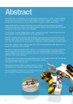
Abstract Pneumatic fenders are extensively used for Ship-to-Ship transfers at sea or in ports. A typical operation will take place at sea with two vessels moored alongside each other at anchor or underway, or in ports during double banking operations, and as vessel-to-berth moored at terminals, docks, jetties. Supply of high quality and reliable fenders that perform effectively under the harshest environmental conditions is an absolute necessity. It is therefore extremely crucial for each and every pneumatic fender to comply fully with the ISO 17357-1:2014 standards. In recent times,...
カタログの2ページ目を開く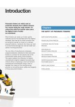
Introduction Pneumatic fenders are widely used as protection elements from collision between two vessels during the cargo transfer. It’s critical that while this transfer takes place, the highest levels of safety are maintained. When fenders are made up of lower quality materials and are not manufactured to the highest standards, they may fail at critical moments such as during the transfer of crude oil in mid-sea exposed locations. Accidents like these can lead to environmental damage and risk the health and safety of working personnel. The new influx of manufacturers employing wrapped...
カタログの3ページ目を開く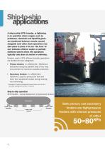
Ship-to-ship applications A ship-to-ship (STS) transfer, or lightering, is an operation where cargoes such as petroleum, chemicals and liquefied gases are transferred between vessels moored alongside each other. Such operations may take place in ports or at sea. The Term ‘at sea’ indicates offshore waters or partially sheltered waters where STS operations typically take place at anchor or underway. Fenders used in STS offshore transfer operations are divided into two categories: Primary fenders: 4 x 4500mmD x 9000mmL* positioned along the parallel body of the ship and provide the maximum...
カタログの4ページ目を開く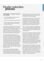
Fender selection process In STS operations, a pneumatic fender must do the following: Absorb 5000-6000KJ of energy in rough conditions for some vessels Create low hull pressures during compression Generate enough stand-off between vessels even after high compressions (over 60% of the fender’s diameter) After contact, the discharge ship and the receiving ship usually have different rotational and linear movements. These movements exert huge amounts of shearing forces on the fenders. Therefore, fenders must be able to withstand shear forces even at very high and very low temperatures while...
カタログの5ページ目を開く
Pneumatic fender manufacturing processes: Conventional vs. wrapped Pneumatic fenders manufactured and supplied by the wrapped manufacturing methods incorporate a bladder at the very foundation of the manufacturing processes. The manufacturing techniques are completely different from a conventional pneumatic fender manufacturing process using a mold. The following section highlights the difference in the two manufacturing methods: PNEUMATIC FENDERS: THE CONVENTIONAL METHOD Pneumatic fenders are produced inside a mold. The mold sits on two rollers to easily rotate the molds during the...
カタログの6ページ目を開く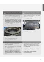
PNEUMATIC FENDERS: THE CONVENTIONAL METHOD PNEUMATIC FENDERS: THE WRAPPED METHOD The manufacturing process starts by detaching the mold into two halves and manually applying the soft unvulcanized outer rubber layer onto the two straight parts after cleaning them thoroughly. bladder is manufactured by joining soft rubber sheets A and vulcanized in the autoclave. Internal pressure is applied by an air inlet valve attached on the one end of the bladder. Aside from Type 1 Single Fenders (net type and one end with no flange opening and no metal parts), fenders with tire and chain nets (CTN...
カタログの7ページ目を開く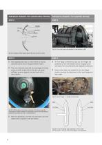
PNEUMATIC FENDERS: THE CONVENTIONAL METHOD PNEUMATIC FENDERS: THE WRAPPED METHOD Fig 14: Tire cord layers are applied on the bladder at 90° Fig 12: Location of the bead ring for the turn up of tire cords. STEP 3 After applying each layer, a hand stitcher is used to manually remove any air trapped between layers. This is an important step and the advantage of making products inside a rigid mold is that one can apply sufficient pressure against the steel mold with a hand stitcher. STEP 3 inner flange is attached to each end. The flanges are An positioned on the inner bladder and are wrapped...
カタログの8ページ目を開く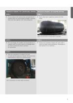
PNEUMATIC FENDERS: THE CONVENTIONAL METHOD PNEUMATIC FENDERS: THE WRAPPED METHOD The two halves of the mold are then connected and an operator enters the mold through the flange to manually stitch each layer together at the mold parting area. Outer rubber layer is applied to construct the final shape. Fig 18: The final shape of a fender before vulcanization STEP 5 The outer flanges are installed, and compressed air is charged inside the mold to check for air leakage before the mold is transferred inside an autoclave for vulcanization. STEP 5 Fenders are completely wrapped with nylon cloth...
カタログの9ページ目を開く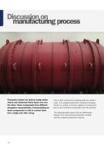
Discussion on manufacturing process Pneumatic fenders are built by laying rubber sheets and rubberized fabric layers one over the other. These components have different elongation characteristics. Preassembling all these components is vital to convert them into a single unit after curing. This is best achieved by building products inside a mold. The wrapped production method of building fenders is unable to achieve rigidity of components due to the limitations associated with the process. The following table shows the key differences between the conventional production method and the...
カタログの10ページ目を開く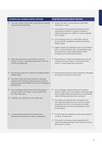
CONVENTIONAL MANUFACTURING PROCESS WRAPPED MANUFACTURING PROCESS Fenders are built on a pre-vulcanized soft bladder instead of in a mold. The entire fender is built inside a mold without using any pre-vulcanized components. The bonding of a pre-vulcanized component with an unvulcanized component is always a challenge in rubber technology as it is difficult to achieve adequate bond strength. s the layering is done on a soft bladder, physical A pressure cannot be applied to enhance the bonding between layers. rganic solvents are ineffectively used to bond different O layers. In case the...
カタログの11ページ目を開くTrelleborg Marine and Infrastructure/トレルボルグ・マリンシステムズのすべてのカタログとパンフレット
-
 SafePilot brochure
20 ページ
-
 Docking & Mooring
88 ページ
-
 AutoMoor Brochure
24 ページ
-
 Fender Systems
86 ページ
-
 DynaMoor
20 ページ
-
 Bollards
28 ページ
-
 SmartDAS Factsheet
2 ページ
-
 TRELLEBORG DYNAMOOR
4 ページ
-
 Surface Buoyancy
24 ページ
-
 SmartMoor Series II
7 ページ
-
 LNG Infographic
8 ページ
-
 SafePilot User Guide
30 ページ
-
 Combined ESDS & SSL
3 ページ
-
 Floating Fenders
48 ページ
-
 Prelude LNG
1 ページ
-
 AutoMoor Datasheet
4 ページ
-
 Buoy Range Table
2 ページ
-
 Hawser Hooks
6 ページ
-
 Guide - Fenders
8 ページ
-
 Barometer Report 3
16 ページ
-
 Barometer Report 2
7 ページ
-
 Capstans
4 ページ
-
 Accessories
10 ページ


カタログアーカイブ
-
 Docking and mooring
2 ページ
