
カタログの抜粋

Product Segments • Industrial Motion TiMOTION’s MA2T series electric linear actuator was specifically designed for applications that face harsh working environments and require heavy-duty and durability. Example applications suitable for the MA2T: Agricultural equipment such as seed spreader, harvesters, grain handlers, combines, tractors…etc. Commercial and industrial applications include commercial lawn mowers, scrubbers and sweepers, material handling equipment, and livestock ventilation systems. Furthermore, the MA2T is a T-Smart (note 1) version actuator that can work with the PGMA (note 2) to achieve the following functionality: - Set up the actuator’s stroke and speed - Multiple signal feedbacks support - Monitor real-time actuator status - Up to 8 actuator synchronization - Built-in safety mechanism - Customized service for BUS required applications (note 3) Note 1: T iMOTION develops T-Smart functionality. With T-Smart, the actuator has a built-in circuit board with a microprocessor that can operate the actuator without a control box. Note 2: P GMA is a software program developed by TiMOTION. Users can install this programmer into the laptop and adjust the actuator parameters directly. Note 3: Please contact your local sales department for further assistance. General Features Max. load Max. speed at max. load Max. speed at no load Retracted length IP rating Stroke Options Voltage Operational temperature range Operational temperature range at full performance 8,000N (push/pull) 5.4mm/s 52.5mm/s ≥ Stroke + 131mm IP69K 25~1000mm Hall sensors, manual drive, Reed sensor on the outer tube, T-Smart 12/24 V DC -40°C~+85°C +
カタログの1ページ目を開く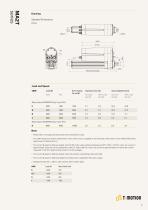
Retracted Length Load and Speed CODE Self Locking Force (N) Motor Speed (5200RPM, Duty Cycle 25%) F Motor Speed (5200RPM, Duty Cycle 10%) K Note 1 Please refer to the approved drawing for the final authentic value. 2 This self-locking force level is reached only when a short circuit is applied on the terminals of the motor. All the TiMOTION control boxes have this feature built-in. 3 The current & speed in table are tested with 24V DC motor under ambient temperature 20°C. With a 12V DC motor, the current is approximately twice the current measured in 24V DC. With a 36V DC motor, the...
カタログの2ページ目を開く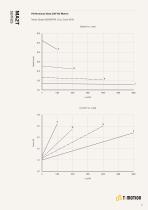
Motor Speed (5200RPM, Duty Cycle 25%) Speed vs. Load 60.0 Performance Data (24V DC Motor)
カタログの3ページ目を開く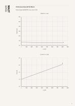
Motor Speed (5200RPM, Duty Cycle 10%) Speed vs. Load 60.0 Performance Data (24V DC Motor)
カタログの4ページ目を開く
Rear Attachment (mm) See page 6 1 = Aluminum casting, clevis U, slot 8.2, depth 12.5, hole 10.2 2 = Aluminum casting, clevis U, slot 8.2, depth 15.0, hole 10.2 3 = Aluminum casting, clevis U, slot 8.2, depth 15.0, hole 12.8 4 = Aluminum casting, clevis U, slot 8.2, depth 15.0, hole 12.2 Front Attachment (mm) See page 7 1 = Iron inner tube with punched hole, without slot, hole 10.2 2 = Iron inner tube with punched hole, without slot, hole 12.2 3 = Iron inner tube with punched hole, without slot, hole 12.8 4 = Aluminum casting, clevis U, slot 8.2, depth 15.0, hole 10.2 5 = Aluminum casting,...
カタログの5ページ目を開く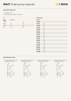
MA2T Ordering Key Appendix Retracted Length (mm) 1. Calculate A+B = Y 2. Retracted length needs to ≥ Stroke+Y A. Front Attach. 4 = luminum casting, clevis U, slot A 8.2, depth 15.0, hole 12.2 3 = luminum casting, clevis U, slot A 8.2, depth 15.0, hole 12.8 2 = luminum casting, clevis U, slot A 8.2, depth 15.0, hole 10.2 1 = luminum casting, clevis U, slot A 8.2, depth 12.5, hole 10.2
カタログの6ページ目を開く
MA2T Ordering Key Appendix Front Attachment (mm) 4 = luminum casting, clevis U, slot A 8.2, depth 15.0, hole 10.2 3 = ron inner tube with punched I hole, without slot, hole 12.8 2 = ron inner tube with punched I hole, without slot, hole 12.2 1 = ron inner tube with punched I hole, without slot, hole 10.2 6 = luminum casting, clevis U, slot A 8.2, depth 15.0, hole 12.8 5 = luminum casting, clevis U, slot A 8.2, depth 15.0, hole 12.2 Direction of Rear Attachment (Counterclockwise) 1 = 90°
カタログの7ページ目を開く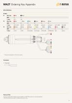
MA2T Ordering Key Appendix Wire Definition DC Moter P1 Wire Color Wire Color Wire Color * The signal wires depend on the chosen options. Connector 1 = Tinned lead Terms of Use The user is responsible for determining the suitability of TiMOTION products for a specific application. TiMOTION products are subject to change without prior notice.
カタログの8ページ目を開くTiMOTION Technologyのすべてのカタログとパンフレット
-
 MA4 Series
9 ページ
-
 TL7 SERIES
4 ページ
-
 TL6 SERIES
4 ページ
-
 TL5 SERIES
3 ページ
-
 TL4 SERIES
4 ページ
-
 TL3 SERIES
7 ページ
-
 PRODUCT CATALOGUE
32 ページ
-
 TA4-series
4 ページ
-
 TA3-series
6 ページ
-
 TA2P-series
4 ページ
-
 TA2-series
4 ページ
-
 TA1-series
4 ページ