
カタログの抜粋

Betriebs- & Wartungsanleitung Operation & Maintenance Hydr. Rollreffanlage Hydraulic Furling Gear Reckmann Yacht Equipment GmbH • SiemensstralSe 37-39 • D-25462 Rellingen info@reckmann.com • www.reckmann.com
カタログの1ページ目を開く
Inhaltsverzeichnis / Index Montageanleitung RF90 / assembly instructions RF90 Produktbeschreibung / product description 3 Tabelle mit Kürzungsmalsen / table of abridgements 4 Bestimmung der Vorstaglànge D / forestay length D 4 Bestimmung der Profillànge B / profile length B 4 Profilmontagehinweise / profile assembly instructions 5 Ablàngen des Profiles / shortening the foil top section 6 Ablàngen des Topschlauches/ shortening the top hose 7 Vorbereitung der Topkappe / preparation of the top cap 8 Montage der Schlàuche und Buchsen / assembly of the bushes and spacers 9 Profilmontage /...
カタログの3ページ目を開く
Packliste für RF 90 / Check list for RF 90 Kunde: Datum: Customer Date Handler / distributor. Bestellnummer / order number. Speziai Walzterminal mit Gewinde Special swage terminal with thread Topterminal:... Sta-lok ...Walzterminal ... Augterminal Topterminal:... Sta-lok ... swage terminal ... eye terminal hydraulicfurler with toggle halyard swivel 2 Schnappschakel für Antrieb und Fallenschlitten snap shackle for furler and halyard swivel lower profile section 3000 mm / 5980 mm standard profile section 3000 mm / 5980 mm standard profile section 1500 mm 1 Untere Gewindeplatte mit Schrauben (...
カタログの4ページ目を開く
spacer tubes 240 mm ( slotted ) spacer tubes 1660 mm ( slotted ) Spacer tubes 500 mm ( marked red ) splice bearing with 2 screws) untere Profilverstarkung lower reinforcement Standardbuchse, bei Profilen R5, R6 und R7, 2-teilige Ausfiihrung standard bearing, the bearings for R5, R6 and R7 profiles are split join connectors ( the connectors for R20, R30 and R40 profiles are split ) VA Einlegekeil fiir Profilverbinder ( 1 Reserve) stainless steel insert for split join connectors ( 1 spare part ) Schraube fiir Profilverbinder ( 2 Reserve ) screw for split join connectors (2 spare parts )...
カタログの5ページ目を開く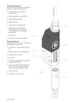
besteht aus folgenden Komponenten: Klemmbacken oder Drahtterminal Product description The hydraulic Twin Furler series RF90 consists 1. gear box cover - black anodized alumini- 2. protective outer cover - high grade steel 3. hydraulic motor - encased 5. socket for emergency manua I drive with standard winch handle 6. bronze screw body with attachment for split collets or wire forestay end. Outer screw body with forestay deck toggle 7. outer screw body 8. couplings for hydraulic hoses
カタログの6ページ目を開く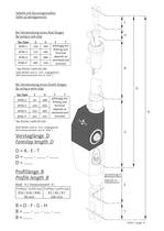
Bei Verwendung eines Rod-Stages (Alle Malse sind in mm angegeben) Bei Verwendung eines Draht-Stages (Alle Malse sind in mm angegeben) Mittel position
カタログの7ページ目を開く
Die Profilmontage ist je nach Profiltyp und Vorstag unterschiedlich. Aus diesem Grund haben wir auf den folgenden Seiten drei ver- schiedene Montageanleitungen erstellt. Fol- gen Sie bitte auf jeden Fall der auf Ihr Profil zutreffenden Montageanleitung. Profile assembly The profile assembly is different according to the type of profiles and the forestay. For this reason we have made three different assembly instructions. Please follow the correct one. forestay : wire from d = 26mm
カタログの8ページ目を開く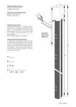
Profile assembly instructions Um das KürzungsmalS C zu erhalten, setzen Sie das Mal? P ( ungekürzte Profillange, siehe Rechnung ein. Kiirzen Sie nun eines der 3000 Diese Sektion ist jetzt die Topsektion. To obtain the measurement C make an entry, in the prepared calculation below, of measure- ments P ( the total length of sections supplied, see page 1) and B (your total required foil sec- tion lengths ) . Shorten one of the 3000 mm standard sections by the length C. This will
カタログの9ページ目を開く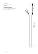
A long spacer tube is provided for the top sec- tion and this will have to be cut to suit. Cut the dimension C also from this spacer tube.
カタログの10ページ目を開く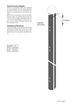
Stecken Sie die beiden Hàlften der Topkappe der beiden Hàlften von der Vorderkante des Profils zur Hinterkante mit den Ñuten ver- Bohren Sie nun zusammen, wie auf der Abbil- dung zu sehen, auf beiden Seiten durch das Profil und die jeweilige Topkappenhàlfte ein Loch mit dem Durchmesser d (siehe Tab. un- ten ). Für die weitere Montage entfernen Sie Insert both ¡naifes of the top cap into the top section and carefully drill a pilot hole ( table for d below ) on each side for the screws pro- vided. Remove the top cap for installation lat-
カタログの11ページ目を開く
und obères Augterminal nach der Beschrei- bung des Herstellers montleren. Cutting the wire headstay Cut the headstay wire according to size D . Mount the eye terminai at the top according
カタログの13ページ目を開く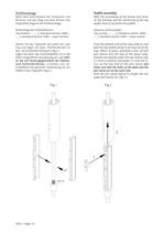
Nach dem Aufschieben der Schlàuche und Buchsen auf das Stag und dem Kiirzen des Topprofiles beginnt die Profilmontage. Profile assembly After the assembling of the bushes and hoses profile start to assemble the profiles. Ziehen Sie das Topprofil von unten bis zum Top und legen Sie zwei Profilverbinder an den rot markierten Schlauch ( Fig.l ). Legen Sie dann die Gewindeplatte (1) in die dafür vorgesehene Aussparung ein und acht- schlielSend die gesamte Verbindung (2) zur From the bottom end of the stay, slide on and feed the top profile along to the top end of the stay. When in place,...
カタログの14ページ目を開く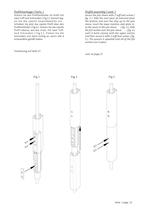
Profilmontage ( Forts. ) Sichern Sie den Profilverbinder im Profil mit zwei Tuff-lock Schrauben ( Fig.3 ). Danach leg- Schieben Sie jetzt das zweite Profil über den Profilverbinder ( Fig.4 ). Sichern Sie das zweite Profil ebenso, wie das erste, mit zwei Tuff- lock Schrauben ( Fig.5 ). Ziehen Sie die Schrauben erst dann richtig an, wenn alle 4 einwandfrei gefalSt haben. Profile assembly ( cont. ) Secure the join sleeve with 2 tuff-lock screws ( fig. 3 ). Slide the next piece of extrusion from the bottom end over the stay up to the join sleeve. Insert the lower stainless steel plate in- to...
カタログの15ページ目を開く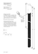
Profile assembly instructions Um dasKürzungsmal? C zu erhalten, setzen SiedasMalS P ( ungekürzte Profillange, siehe Seite 1 ) und das Mal? B in die zweite Rech- nung ein. Kiirzen Sie nun eines der 6000 mm langen Standardprofile um das Kurzungsmal? Diese Sektion ist jetzt die Topsektion. To obtain the measurement C make an entry, in the second calculation bellow, of measure- ments P ( the total length of sections supplied, see page 1) and B (your total required foil sec- tion lengths ) . Shorten one of the 6000 mm standard sections by the length C. This will
カタログの16ページ目を開くReckmann Yacht Equipment GmbHのすべてのカタログとパンフレット
-
 MF-SYSTEMS
3 ページ
-
 UD Systems
3 ページ
-
 EF90 Systems
3 ページ
-
 CZ Systems
3 ページ
-
 sunFLIP
11 ページ
-
 CZ-E
CZ-E2 ページ
-
 Masts
Masts4 ページ
-
 Rigging Hydraulics
20 ページ
-
 Cylinders HCL
2 ページ
-
 PP II
PP II6 ページ
-
 PP IV
PP IV6 ページ
-
 PP III
6 ページ
-
 PP I - 3 KW
6 ページ
-
 PP I - 1,5 & 2 KW
6 ページ


カタログアーカイブ
-
 Cylinders HCL-LS
2 ページ
-
 Integral adjusters
2 ページ
-
 CT8t - brochure
1 ページ
-
 CT8te - brochure
1 ページ
-
 maxJ
maxJ1 ページ
-
 RS3000
1 ページ
-
 RC30/40
2 ページ
-
 RS2000
6 ページ
-
 RF90 - brochure
6 ページ
-
 Masts brochure
4 ページ
-
 EF90 brochure
6 ページ
-
 PowerPacks brochure
6 ページ

