グループ: Noris Group

カタログの抜粋

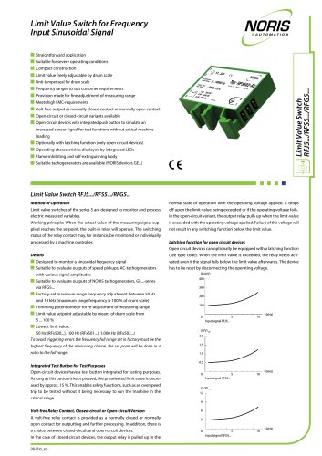
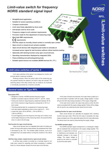
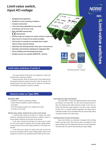
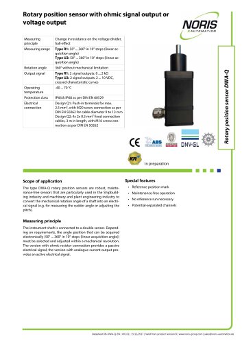
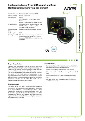
NORISYS 4 LT4 Control Lever System Single lever and double lever setups Several available scales, separated for both handles LED band for position indication of active lever for each handle Optional electrical shaft functionality for each handle with force feedback Control lever system NORISYS4-LT4 n 2 separated CANbus interfaces (option) 1 RS-485 interface (optional) 1 scale illumination input (dimmable) 2 digital inputs, galvanically isolated (optional) 2 analogue outputs 4 ... 20 mA (one for each handle, optional) Extended operating temperature range -25°C ... +70°C IP56 front side Application range The NORISTAR control lever system is designed for ship propulsion plant applications in accordance to marine certification requirements. The lever can be equipped in three levels, starting from a mechanical setup with potentiometric signal outputs, basic electronic equipment with analogue standard signal output 4 ... 20 mA for each handle and as full electric version with integrated data interface and optional electrical shaft system onboard. The full electronic version is equipped with several data interfaces as well as analogue standard signal outputs. The full electronic equipped control lever can be interconnected to an automation system via redundant or single CANbus as well as by using the integrated RS-485 interface with Modbus-RTU or NORISYS 4 ExtBus protocol. The electronic control lever can be used as gateway to add NORISYS 4 and NORISTAR 4 extension units to an automation system. All versions provide a signal output for each handle, positioning indication and dimming of the scale illumination. The data interfaces are short-circuit proved and 24 V protected. Description In relation to its area of application the lever can be equipped as single or double lever as well as control lever chain. The portfolio of standard and customer-specific scales matches a wide range of applications. Direct wiring of standard industrial signal cables is provided by 2.5 mm² terminal blocks. The design as a plug-and-play component in the basic and full electronic version requires no calibration handling on customer side. The full electronic version is equipped with a high performance ARM processor, which calculates the handle positions, controls the integrated LED band as well as the stepper motors of the optional electrical shaft system and powers the data interfaces. The integrated LED band for each handle is a precise visualisation to indicate the current position of the active control lever and to support the operator during control position transfer. An optional electrical shaft system provides automatic alignment of each handle according to the position of the active control lever in the network. The ESS option uses the existing network interconnection between all levers and the remote control system and requires no separate control hardware. Mechanical Versions The mechanical design allows a setup of several application specific versions. The lever can be equipped as single and double handle. For main propulsion systems a base socket can be used to tend the device towards the operator. For thruster applications the control lever can be mounted rotated by 90°. The handle can be mounted according to application and user requirements. For similar propulsion plants it is possible to establish a control lever chain by connecting the control levers with a reversible mechanical linkage. Datasheet DB-NORISYS4-LT4-EN | V01.01 | 04/12/2019 | Valid from product revision Rev. M2.0 | www.noris-group.com | sales@noris-automation.d
カタログの1ページ目を開く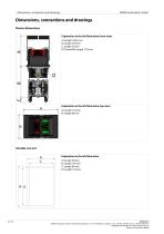
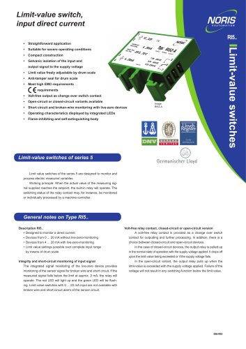
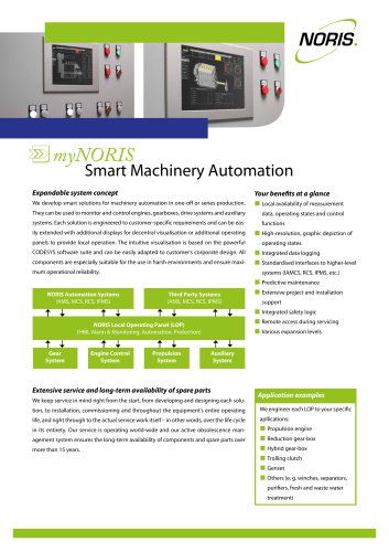
| Dimensions, connections and drawings NORIS Automation GmbH Dimensions, connections and drawings Device dimensions Explanation to the left illustration (front view) A) Length 128.5 mm B) Length 128 mm C) Length 20 mm D) Thread M4, length 17.8 mm Explanation to the left illustration (top view) A) Length 144 mm B) Length 98 mm Console cut-out Explanation to the left illustration A) Length 98 mm B) Length 144 mm C) Length 86 mm D) Length 132 mm NORIS Automation GmbH | Friedrich Barnewitz Str. 10 | 18119 Rostock | Germany | Tel: +49 381 519 944-0 | Fax: +49 381 519 944-4...
カタログの2ページ目を開く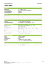
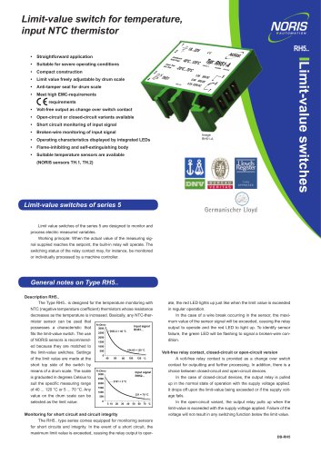
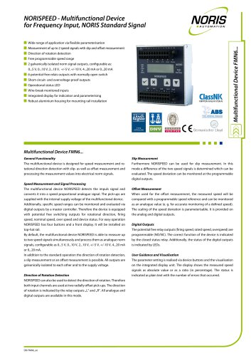
NORIS Automation GmbH Technical data Connection Supply voltage Current consumption 0.15 ... 1.5 A according to level of equipment Reverse voltage protection Over voltage protection Interfaces CANbus (optional) Electrical connections Terminals for cable profile 2.5 mm² In-/Output Digital inputs 1 x Input, 1x Output, galvanically isolated Illumination regulation input Environmental influences Operating temperature Climatic test Storage temperature Vibration resistance IEC 61000-4-2: ± 6 kV/Contact Discharge; ± 8 kV/Air Discharge HF-interference immunity Interference emission Mechanical...
カタログの3ページ目を開く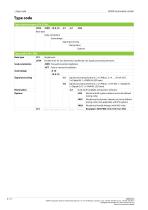
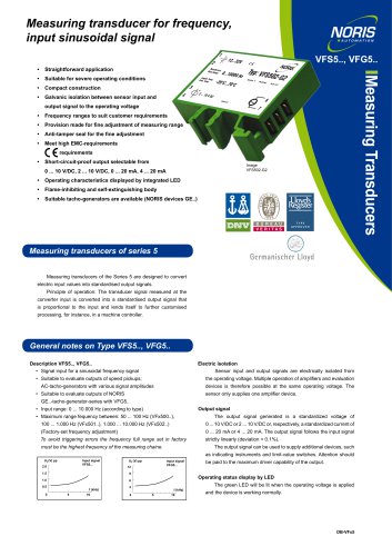
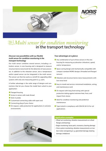
NORIS Automation GmbH Type code Type code structure LT4, LTD4… LTD4 Base type Scale orientation Scale design Signal processing Illumination Options Type code LT4, LTD4 Base type Single lever Double lever for two demands, handled by one signal processing electronic Scale orientation -FWD Forward oriented installation -AFT Astern oriented installation Scale design Signal processing Signal processing electronic, 2 x CANbus, 2 x 4 … 20 mA OUT, 2 x Digital IN, 1 x PWM IN, LED band Signal processing electronic, 2 x CANbus, 1x RS-485, 1 x Digital IN, 1x Digital OUT, 1 x PWM IN, LED band Scale with...
カタログの4ページ目を開くNORIS Group GmbHのすべてのカタログとパンフレット
-
 Unique Yacht Automation
16 ページ
-
 Datasheet TAV131
3 ページ
-
 Datenblatt VFS5
2 ページ
-
 Datasheet PAx9
6 ページ
-
 Datasheet RG5
2 ページ
-
 Datasheet VFW5
2 ページ
-
 Datasheet RP5, RPT5
2 ページ
-
 Datasheet NIR3 NIQ3
20 ページ
-
 Datasheet VD61
6 ページ
-
 Datasheet FA13
14 ページ
-
 Datasheet NIQ31
16 ページ
-
 NORIS Marine Overview
13 ページ
-
 Datasheet FA54
11 ページ
-
 NORIS Brochure
15 ページ
-
 Datasheet TP31 TH31
5 ページ
-
 Datasheet EOT
6 ページ
-
 Datasheet DWA
4 ページ
-
 Datasheet TP23
4 ページ
-
 Datasheet VF5
2 ページ
-
 Flyer NORISYS 4 CPU
2 ページ
-
 Datasheet RFW5
2 ページ
-
 Datasheet RTK5
2 ページ
-
 Datasheet RFJ5
2 ページ
-
 Datasheet VTK5
2 ページ
-
 Datasheet RF5
2 ページ
-
 Datasheet RI5
2 ページ
-
 Datasheet RFG5
2 ページ
-
 Datasheet VPT5
2 ページ
-
 Datasheet RH5
2 ページ
-
 Datasheet VFS5
2 ページ
-
 Datasheet RH41M
2 ページ
-
 Datasheet RW5
2 ページ
-
 Datasheet VMP70
3 ページ
-
 Datasheet VP5
2 ページ
-
 Datasheet NADS3
2 ページ
-
 Datasheet NAD2
2 ページ
-
 Datasheet NAD1
2 ページ
-
 Flyer NORISYS 4
2 ページ


カタログアーカイブ
-
 Datasheet GE12
2 ページ
-
 Datasheet GE14
2 ページ