グループ: Noris Group

カタログの抜粋

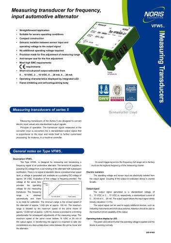
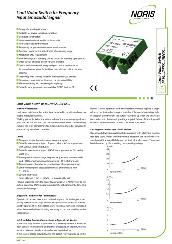
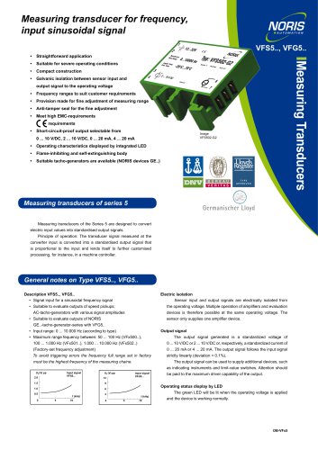
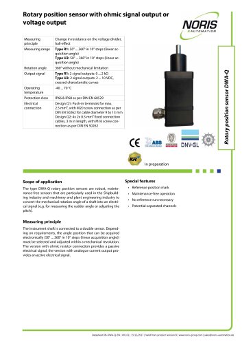
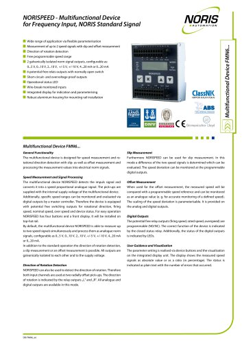
Non-contacting speed sensor type FA54 with aluminium flange and stainless steel sensor tube Non-contacting Measuring principle Hall principle Frequency range Supply voltage Scanning object Ferromagnetic materials Protection class Flange: Aluminium Measuring area: Stainless steel Measuring channels Scanning type Output signal and 1 square wave signal or signal type 1 square wave signal + 1 inverted square wave signal or 2 square wave signals or 2 square wave signals + 1 status signal or 2 square wave signals + 2 inverted square wave signals Options Inverted output signals; galvanically isolated output signals; status signal for direction of rotation detection Application range Special features Speed sensors type series FA54 are compact and robust flange sensors with type approval from all common ship class societies. They are suitable for scanning ferromagnetic objects, such as toothed wheels, bolt heads, drillings/boreholes, gaps, grooves or impulse bands. • Robust and high quality housing: IP68 pressure-tight The different sensor variants allow measurements with up to two measuring channels and up to four output signals for measurement of frequencies from 0 to 20 kHz. Thus, they are suitable for standstill detection and for rotational direction detection by using phase shifted signals. Different sensor tube lengths and connection outlets as well as your tailor-made solution on request enable an adaptation to almost any application. Do not hesitate to contact our technical sales team (sales@noris-group.com) and ask for a quotation. • Excellent vibration and shock resistance • High degree of EMC immunity for difficult electrical environment • Connection outlet straight or lateral; with protective tubing on request • Up to four output signals, on request available with one status signal for rotational direction detection, on request with two galvanically isolated output signals • Due to its design and its approvals especially suitable for shipbuilding industry Measuring principle Hall principle A field of a magnet generates a constant voltage in the Hall elements. Ferromagnetic objects with an interrupted surface cause the Hall voltage to change as they pass the Hall elements. The frequency of the change of the Hall voltage is proportional to the speed of movement (rotational speed). The speed sensor converts this change into an electric signal. Datasheet DB-FA54-EN | V01.01 | 18/06/2021 | Valid from product revision A | www.noris-group.com | sales@no
カタログの1ページ目を開く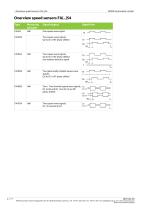
| Overview speed sensors FA[..]54 NORIS Automation GmbH Overview speed sensors FA[..]54 Type Measuring principle Signal outputs One square wave signal Two square wave signals, Q2 to Q1 is 90° phase shifted Signal form Two square wave signals, Q2 to Q1 is 90° phase shifted, one rotation direction signal Two galvanically isolated square wave signals, Q2 to Q1 is 90° phase shifted Two + Two inverted square wave signals, Q1 to Q2 and Q1_N to Q2_N are 90° phase shifted Two square wave signals, Q1_N inverted to Q1 NORIS Automation GmbH | Muggenhofer Str. 95 | 90429 Nuremberg | Germany | Tel: +49...
カタログの2ページ目を開く
NORIS Automation GmbH Dimensions, connections and drawings | Dimensions, connections and drawings Dimensions and mounting drawing Explanation to the left illustration C Fig.: Borehole for FA[..]54_Top view Recommended fixing: Hexagon socket screw DIN912 M6x20 with spring washer. NORIS Automation GmbH | Muggenhofer Str. 95 | 90429 Nuremberg | Germany | Tel: +49 911 3201-220 | Fax: +49 911 3201-150 | sales@noris-group.com | www.noris-group.com Errors and omissions excepted
カタログの3ページ目を開く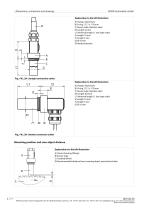
| Dimensions, connections and drawings NORIS Automation GmbH Explanation to the left illustration A) Flange: Aluminium B) O-ring 17.17 x 1.78 mm C) Sensor tube: Stainless steel D) Length 34 mm L1) Nominal length L1 (see type code) E) Length 10 mm F) Length 5 mm G) Ø 16 mm H) Bend protection Explanation to the left illustration A) Flange: Aluminium B) O-ring 17.17 x 1.78 mm C) Sensor tube: Stainless steel D) Length 36.5mm L1) Nominal length L1 (see type code) E) Length 10 mm F) Length 5 mm G) Ø 16 mm Mounting position and scan object distance Explanations to the left illustration A) Sensor...
カタログの4ページ目を開く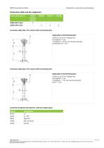
NORIS Automation GmbH Dimensions, connections and drawings | Connection cables and pin assignment Connection type -X Cable with 4 wires Cable with 6 wires Connection cable type -X for sensors with 4 connecting wires Explanation to the left illustration A) Wires 4 x 0.33 mm2 halogen-free B) Length 80 ±10 mm C) Length K1 ± 5% (K1 see customer drawing) D) Diameter 4.6 ±0.2 mm Connection cable type -X for sensors with 6 connecting wires Explanation to the left illustration A) Wires 6 x 0.33 mm2 halogen-free B) Length 80 ±10 mm C) Length K1 ± 5% (K1 see customer drawing) D) Ø 7 ±0.5 mm...
カタログの5ページ目を開く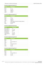
| Dimensions, connections and drawings NORIS Automation GmbH Connection assignment for type FA[..]Z Connection assignment for type FA[..]S Status output for direction of rotation detection Connection assignment for type FA[..]D Connection assignment for type FA[..]Q Connection assignment for type FA[..]Y NORIS Automation GmbH | Muggenhofer Str. 95 | 90429 Nuremberg | Germany | Tel: +49 911 3201-220 | Fax: +49 911 3201-150 | sales@noris-group.com | www.noris-group.com Errors and omissions excepted
カタログの6ページ目を開く
NORIS Automation GmbH Dimensions, connections and drawings | Elementary circuit diagram FAH54, FAHZ54 Elementary circuit diagram FAHS54 Q2 Elementary circuit diagram FAHD54 Elementary circuit diagram FAHQ54, FAHY54 NORIS Automation GmbH | Muggenhofer Str. 95 | 90429 Nuremberg | Germany | Tel: +49 911 3201-220 | Fax: +49 911 3201-150 | sales@noris-group.com | www.noris-group.com Errors and omissions excepted
カタログの7ページ目を開く
| General technical data NORIS Automation GmbH General technical data Electrical connection Supply voltage See specific technical data Nominal voltage See specific technical data Current consumption See specific technical data Reverse voltage protection Over voltage protection Cable end, customized connections acc. customer drawing Recommended cable length Used cable cross section Electrical output Measuring channels See specific technical data Output signal and signal type See specific technical data Output stage Push-pull amplifier Continuous short circuit protection Galvanic isolation...
カタログの8ページ目を開くNORIS Group GmbHのすべてのカタログとパンフレット
-
 Unique Yacht Automation
16 ページ
-
 Datasheet TAV131
3 ページ
-
 Datenblatt VFS5
2 ページ
-
 Datasheet PAx9
6 ページ
-
 Datasheet RG5
2 ページ
-
 Datasheet VFW5
2 ページ
-
 Datasheet RP5, RPT5
2 ページ
-
 Datasheet NIR3 NIQ3
20 ページ
-
 Datasheet VD61
6 ページ
-
 Datasheet FA13
14 ページ
-
 Datasheet NIQ31
16 ページ
-
 NORIS Marine Overview
13 ページ
-
 NORIS Brochure
15 ページ
-
 Datasheet TP31 TH31
5 ページ
-
 Datasheet EOT
6 ページ
-
 Datasheet DWA
4 ページ
-
 Datasheet TP23
4 ページ
-
 Datasheet VF5
2 ページ
-
 Flyer NORISYS 4 CPU
2 ページ
-
 Datasheet RFW5
2 ページ
-
 Datasheet RTK5
2 ページ
-
 Datasheet RFJ5
2 ページ
-
 Datasheet VTK5
2 ページ
-
 Datasheet RF5
2 ページ
-
 Datasheet RI5
2 ページ
-
 Datasheet RFG5
2 ページ
-
 Datasheet VPT5
2 ページ
-
 Datasheet RH5
2 ページ
-
 Datasheet VFS5
2 ページ
-
 Datasheet RH41M
2 ページ
-
 Datasheet RW5
2 ページ
-
 Datasheet VMP70
3 ページ
-
 Datasheet VP5
2 ページ
-
 Datasheet NADS3
2 ページ
-
 Datasheet NAD2
2 ページ
-
 Datasheet NAD1
2 ページ
-
 Flyer NORISYS 4
2 ページ


カタログアーカイブ
-
 Datasheet GE12
2 ページ
-
 Datasheet GE14
2 ページ