
カタログの抜粋
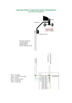
Instromet Wind / Temperature Sensor wiring diagram Yellow = Wind Direction input Blue = Wind Speed input Green = Temp input White = Temp input
カタログの1ページ目を開く
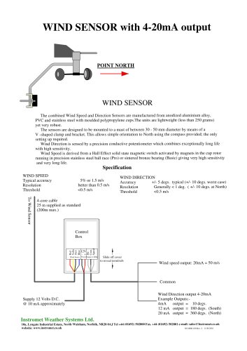
Installation Instruction Sensor wiring The six core cable should be connected to the individual sensor via the terminal block on the sensor bracket. This can be accessed by removing the black cover, where a wiring colour identification label will be found. Roof Top Wind/Temperature Sensor This unit should be mounted on a mast of 25-50mm (1-2inches) in diameter, as high and as far away as possible from chimneys, roof peaks, buildings, trees and transmitter aerials which may cause wind turbulence or interference. Where possible the roof top wind sensor should be mounted at least 2 metres...
カタログの2ページ目を開くInstromet Weather Systems Ltdのすべてのカタログとパンフレット


商品比較を空にする