カタログの抜粋

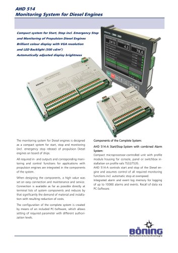
• Compact system for starting, stopping, and monitoring various engines • Alarm and monitoring system designed for maritime use according to the classification societies' guidelines (ABS, BV, CRS, DNV GL, LR, RS) • Additional grid monitoring device for monitoring 3-phase current and frequency • Expandable to monitor for example gearboxes and propellers System Overview The compact system AHD 504 / 514 has been designed and optimized for monitoring diesel engines. It provides all required functions for starting and stopping the engine as well as monitoring all required measuring points. The device AHD 504 A / 514 A serves as the central unit and monitors the connected engine electronics. An appropriate alarm is triggered when an alarm limit is reached. The data are displayed on a compact 5.7" Color Display AHD 514 / AHD 514 OB B which also provides the start / stop function. The Safety System AHD 514 S monitors the redundant sensors required by the classification societies and activates a safety stop if an alarm occurs. An emergency stop system with separate power feed has also been integrated. The additional device AHD 504 NG allows the monitoring and measuring of the supply or generator voltage and frequency. Every system AHD 504 / 514 can be extended with the binary data stations AHD-PS 1 5, AHD-PS 30, AHD-PS 47, the relay station AHD-R101, and the data station AHD-SAS 15. All components have undergone a type approval procedure according to the regulations of the classification societies (for details see the respective device). The devices communicate via a common designated CAN bus. This CAN bus can also be used to display the engine data on for example a Panel PC AHD 1215 F. The second CAN interface of AHD 504 A or AHD 514 A can be used to receive and send engine data in the protocol J1939 and to connect various engine control units (MAN EDC, EMC, EMR, ECU). The 56 most recent alarms can be displayed on AHD 514 OP. More logged events can be read with the configuration software DeviceConfig. The individual components of AHD 504 and AHD 514 can be freely combined with one another for various applications (for example main engine control and monitoring, generator voltage monitoring, etc.). Thus, an application specific and customized system is available for every application. ii Bonino Automationstechnologie
カタログの1ページ目を開く
Alarm System AHD 504 A / AHD 514 A: The Alarm System AHD 504 A / AHD 514 A provides 14 analog and binary inputs, one engine speed input (pickup), three binary inputs, and six control inputs. All inputs can be monitored with configurable alarm limits, and they can trigger a corresponding alarm. Functions, such as Start, Stop, Start Blocking, and Overspeed Test, are activated at separate control inputs. Three relay outputs are used to control the stopping solenoid, the starter, and a signal horn. Error messages are forwarded to a higher-level alarm system at a collective alarm output. An...
カタログの2ページ目を開く
Dimensions W x H x D 173 mm x 128 mm x 55 mm (height including plug connector Inputs 20 inputs, relative to device's ground (GND): - 9 x analog (selection of 4-20 mA / PT1000/bin with jumper) - 2 x analog (selection of NiCrNi / 0-32 V with jumper) - 3 x binary (contact / Bedia with wire break monitoring) - 6 x binary (control inputs) 1 x engine speed input (pickup, galvanically isolated) Outputs 1 x transistor 8 A (32 VDC), wire break monitored, short-circuit- proof (for solenoid or operation solenoid) 4 x relay 3 A (32 V DC, potential-free) 1 x transistor (32 V / 25 mA) 2 x LED indicators...
カタログの3ページ目を開く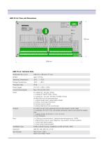
AHD 514 A: Technical Data Dimensions W x H x D 238 mm x 128 mm x 77 mm Inputs 6 x analog (4 - 20 mA) / binary 3 x analog (PT100/PT1000) / binary 3 x analog (4 - 20 mA) / (PT100 / PT1000) / binary Analog inputs can be parameterized 1 x engine speed input, galvanically isolated 2 x binary, wire break monitored 8 x binary (control inputs) 2 x binary (electronic fuse monitoring) Outputs 8 x relay 6 A (32 V DC), potential-free (control outputs, starter relay) 2 x transistor, 8 A (32 V DC), wire break monitored, short-circuit-proof for engine stop 1 x analog output (4-20 mA / 1-5 V / 2-10 V) 2 x...
カタログの4ページ目を開く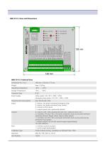
AHD 514 S: Technical Data Dimensions W x H x D 148 mm x 128 mm x 77 mm Power Supply Safety system: 24 V DC ( + 30% / -25%) Emergency stop system: 24 V DC ( + 30% / -25%) Power/Current Consumption Max. 98 mA (24 V DC) Inputs 2 x binary, wire break monitored (emergency stop) 5 x binary, wire break monitored (stop criteria) 5 x binary (control inputs) 1 x engine speed input, galvanically isolated Outputs 4 x relay 6 A (32 V DC), potential-free (for horn, collective alarm, etc.) 2 x transistor, 8 A (32 V DC), wire break monitored, short-circuit-proof (solenoid / operating solenoid, flapper...
カタログの5ページ目を開く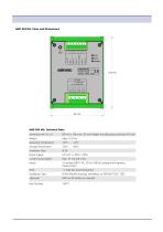
AHD 504 NG: Technical Data Dimensions W x H x D 95 mm x 128 mm x 55 mm (height including plug connector 65 mm) Inputs 3 x analog (500 V AC, 50 Hz / 60 Hz) voltage and frequency measurement Ports 1 x CAN bus (communication) Installation Type Profile Module housing, installation on DIN Rail TS32 / TS35 Approvals DNV GL, RS (others on request)
カタログの6ページ目を開く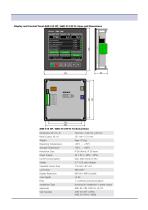
Dimensions W x H x D Panel Cutout, W x H Weight Operating Temperature Storage Temperature Protection Class Power Supply Current Consumption Display Viewable Screen Area Luminosity Display Resolution Color Depth Ports Installation Type Approvals Item Number 144 mm x 144 mm x 43 mm 131 mm x 131 mm Appr. 0.5 kg -30°C ... +70°C -50°C ... +85°C IP 56 (front), IP 20 (rear) 24 V DC ( + 30% / -25%) Max. 200 mA (24 V DC) 5.7” LCD color display 116 mm x 87 mm 500 cd/m2 640 (h) x 480 (v) pixels 15 bit 1 x CAN bus (communication) Housing for installation in panel cutout ABS, BV, CRS, DNV GL, LR, RS AHD...
カタログの7ページ目を開く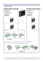
Application Example Auxiliary Engine / Generator - Engine Speed Control (Speed Up/Down) - Communication with Various Engine Control Units - Type Approved by ABS, BV, CRS, DNV GL, LR, RS Propulsion Engine System Dynamic Alarm Limits and History Optional Extensions: e.g. Gearbox, CCP Type Approved by ABS, BV, CRS, DNVGL, LR, RS Display & Operation Unit AHD514 0PB Modbus RTU External Ship Alarm System Boning Automationstechnologie GmbH & Co. KG • Am Steenover 4 • D-27777 Ganderkesee • E-Mail:info@boening.com • www.boeninq.com PaB-1269 V7 Rev.: Nov 9th, 2018, Approved 11/09/2018 ScA • Texts and...
カタログの8ページ目を開くBöning Automationstechnologie GmbH & Co. KGのすべてのカタログとパンフレット
-
 AHD-DPS02 System
8 ページ
-
 AHD-S 201
4 ページ
-
 AHD 882
4 ページ
-
 AHD-SAS 15
4 ページ
-
 AHD-UIC
2 ページ
-
 AHD-DPS02
4 ページ
-
 AHD-POS 10
4 ページ
-
 AHD-WOP
2 ページ
-
 AHD 1119 G
2 ページ
-
 AHD 1219 F
2 ページ
-
 AHD 1119 F
2 ページ
-
 AHD-WNL
4 ページ
-
 AHD 406
3 ページ
-
 AHD 414A
4 ページ
-
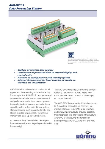 AHD-DPU 9
2 ページ
-
 AHD-RB6
6 ページ
-
 AHD-UCC
2 ページ
-
 8794
87945 ページ
-
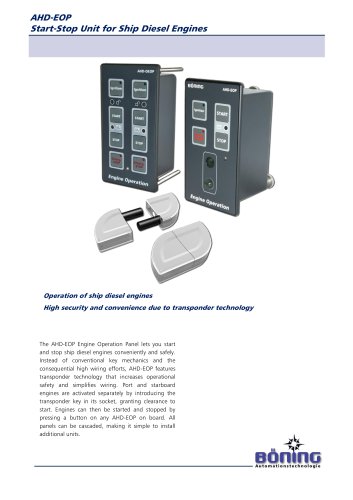
 AHD-EOP/ AHD-DEOP
2 ページ
-
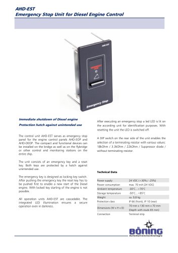 AHD-EST
2 ページ
-
 AHD-SLPV2
4 ページ
-
 AHD-WAOP
2 ページ
-
 AHD 1124 G
2 ページ
-
 AHD 414
4 ページ
-
 AHD-DRM R
2 ページ
-
 AHD-SLP V2
4 ページ
-
 AHD-GAP F
2 ページ
-
 AHD- S 201
4 ページ
-
 Cabin Control System
8 ページ
-
 Selector Switch A250
5 ページ
-
 AHD-VSC CF
12 ページ
-
 AHD-VSC C
12 ページ
-
 2014 AHD 504 / AHD 514
10 ページ
-
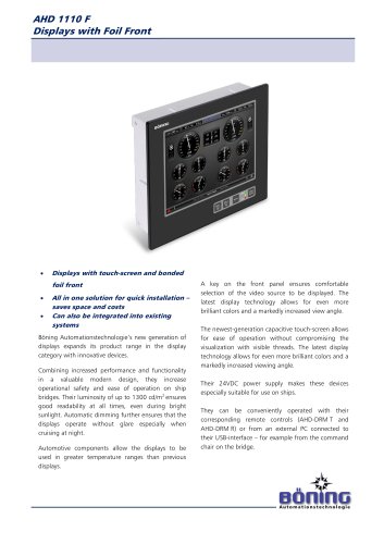 AHD 1110 F
2 ページ
-
 AHD 1310 F
2 ページ
-
 Catalog Ship Automation
88 ページ
-
 AHD 1224 G
2 ページ
-
 HM-Series
8 ページ
-
 AHD-VC 711
12 ページ
-
 AHD 880 E
4 ページ
-
 AHD 880 TC
2 ページ
-
 AHD 880 G
2 ページ
-
 AHD 514 A
4 ページ
-
 AHD-EOP
2 ページ
-
 AHD-S 201
4 ページ
-
 AHD_882
4 ページ