Group: Trelleborg

Catalog excerpts

Fender Systems PRODUCT BROCHURE
Open the catalog to page 1
The Smarter Approach The smarter approach for a more efficient port Transferring know-how for smarter LNG Connect with The Smarter Approach Visit: www.trelleborg.com/marineandinfrastructure Connect: Trelleborg-Marine-and-Infrastructure Discover: TrelleborgMarineandInfrastructure Converse: @TrelleborgMI Explore: Marineandinfrastructure Discover: TrelleborgMarineandinfrastructure Materials best practice for a smarter port The demanding nature of commercial ports and terminals means you need partnership that provides much more than technically superior products and technologies. You need to...
Open the catalog to page 2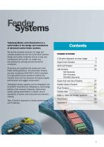
Fender Systems Trelleborg Marine and Infrastructure is a world leader in the design and manufacture of advanced marine fender systems. We provide bespoke solutions for large and complex projects all over the world. Best practice design and quality materials ensure a long, low maintenance service life, no matter how demanding the working and environmental conditions. All fenders are supplied fully tested and meet PIANC 2002 guidelines. Our pneumatic fenders are also completely ISO17357-1:2014 compliant. Our high performance solutions combine low reaction force and hull pressure with good...
Open the catalog to page 3
A Smarter Approach at every stage A smarter approach to… CONSULTATION Consultation from the earliest project phase to ensure the optimum fender, mooring, navigation and transfer solutions are specified, with full technical support from our global offices. Conceptual design in your local office – with full knowledge of local standards and regulations, delivered in your language – for optimized port and vessel solutions. Concepts are taken to our Engineering Center’s of Excellence where our team generates 3D CAD designs, application-engineering drawings, a bill of materials, finite...
Open the catalog to page 4
Across our entire product range, stringent testing comes as standard at every step in our in-house manufacturing process. We ensure that life-cycle and performance of our entire product range meets your specifications, and more. Dedicated project management, from solution design right the way through to on site installation support. We design products and solutions that always consider ease of installation and future maintenance requirements. Local support on a truly global scale, with customer support teams all over the world. And this service doesn’t stop after a product is installed. You...
Open the catalog to page 5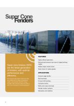
Super Cone Fenders FEATURES Highly efficient geometry Super cone fenders (SCN) are the latest generation of fenders, with optimal performance and efficiency. The conical body shape makes the SCN very stable even at large compression angles, and provides excellent shear strength. With overload stops the SCN is even more resistant to overcompression. Minimal performance loss even at large berthing angles Stable shape resists shear Wide choice of rubber grades APPLICATIONS General cargo berths Bulk terminals Oil and LNG facilities Container berths RoRo and cruise terminals Parallel motion...
Open the catalog to page 6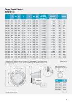
Super Cone Fenders DIMENSIONS H SCN 300 F0.9- 1.8 ANCHORS / HEAD BOLTS ^ F1.9- 3.1 ANCHORS / HEAD BOLTS ^ ^ Fender anchors / head bolts indicated are based on a particular grade of steel. Please contact our local office for precise size, material and type for different grades of fenders pertaining to the project requirements. Some SCN sizes have a modified flange for reduced shipping dimensions.
Open the catalog to page 7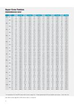
Super Cone Fenders PERFORMANCE DATA* F 0.9^ * For explanation of CV and RPD, please refer to note on page 9-10. ^ Fender grades below F0.9 are available upon request. [Units: kNm, kN] Note: Refer to Index page 89 for 100% natural rubber in a compound.
Open the catalog to page 8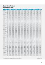
Super Cone Fenders PERFORMANCE DATA* F 2.1 * For explanation of CV and RPD, please refer to note on page 9-10.
Open the catalog to page 9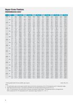
Super Cone Fenders PERFORMANCE DATA* F 0.9^ ^ Fender grades below F0.9 are available upon request. *Note: 1. CV: performance data at slow speed constant velocity (2-8 cm/min) compression at 23 ± 5°C temperature and 0° compression angle. 2. RPD: Rated performance data, in accordance with PIANC with initial high speed berthing velocity 0.15 m/s. RPD = CV (performance) x VF (velocity factor for Natural and Synthetic rubber blend) x TF (temperature factor) x AF (angle factor). RPD is reported at 23 ± 5°C temperature and 0° compression angle, therefore TF = 1, AF = 1.
Open the catalog to page 10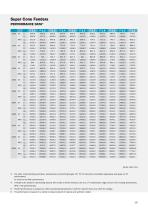
Super Cone Fenders PERFORMANCE DATA* F 2.1 CV RPD [Units: kNm, kN] 3. For other initial berthing velocities, temperature and berthing angle, VF/ TF/ AF should be calculated separately and apply on CV performance to come to the final performance. 4. If fenders are tested in decreasing velocity (DV) mode at initial velocity 0.15 m/s, 0° compression angle and 23 ±5°C testing temperature, 5. Fender performance is subject to ±10% manufacturing tolerance (+10% for reaction force and -10% for energy). 6. CV performance is based on a rubber compound blend of natural and synthetic rubber.
Open the catalog to page 11
Super Cone Fenders INTERMEDIATE DEFLECTIONS Di (%) Nominal rated deflection may vary at RPD. Refer to the Performance Tolerances table in the Fender Application Design Manual. Generic curve shown. Actual curve geometry may vary depending on grade, temperature, velocity and angle. ANGLE FACTOR (AF) TABLE ENERGY FACTOR REACTION FACTOR Energy & Reaction Angle Correction Factors Factors Value The graph shows fender performance with no chain restraints up to 12 degrees and chain restraints for angles above 12 degrees. Fender is fitted with a standard frontal frame. Angle (degrees) Energy factor...
Open the catalog to page 12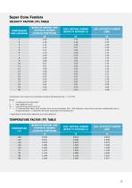
Super Cone Fenders VELOCITY FACTOR (VF) TABLE COMPRESSION TIME (SECONDS) BLEND OF NATURAL AND SYNTHETIC RUBBER (CATALOG COMPOUND) VF 100% NATURAL RUBBER (REFER TO APPENDIX A) Compression time needs to be calculated using the following formula: t = d/(ƒ*Vd) Where: t = d = Vd = ƒ = compression time (seconds)* rated deflection (mm) initial berthing velocity (mm/s) 0.74 deceleration factor (Peak reaction force occurs at between 30% - 40% deflection, where there has been a deceleration due to energy absorption. ƒ represents the factor associated with deceleration.) * Applicable for both partial...
Open the catalog to page 13All Trelleborg Marine and Infrastructure catalogs and brochures
-
 SafePilot brochure
20 Pages
-
 Docking & Mooring
88 Pages
-
 Pneumatic Fender infographic
1 Pages
-
 Pneumatic Fenders brochure
28 Pages
-
 Fender Application Design Manual
88 Pages
-
 Multipurpose and Tug Fenders
44 Pages
-
 Rolling Fenders and Safety
18 Pages
-
 AutoMoor Brochure
24 Pages
-
 DynaMoor
20 Pages
-
 Bollards
28 Pages
-
 Docking and mooring
2 Pages
-
 Solid SmartFender Factsheet
2 Pages
-
 Ship-Shore Links Factsheet
4 Pages
-
 SmartDAS Factsheet
2 Pages
-
 TRELLEBORG DYNAMOOR
4 Pages
-
 SmartDock ® Display Board
4 Pages
-
 Docking & Mooring
88 Pages
-
 Surface Buoyancy
24 Pages
-
 SmartMoor Series II
7 Pages
-
 Performance Monitoring
3 Pages
-
 Universal Safety Link
3 Pages
-
 TRELLEBORG’S Tugger Winch
2 Pages
-
 LNG Infographic
8 Pages
-
 SafePilot User Guide
30 Pages
-
 Safepilot SmartPort System
16 Pages
-
 Combined ESDS & SSL
3 Pages
-
 Ship Shore Link System
3 Pages
-
 Emergency Shutdown Link
3 Pages
-
 Floating Fenders
48 Pages
-
 Prelude LNG
1 Pages
-
 AutoMoor Datasheet
4 Pages
-
 SafePilot CAT XT System
2 Pages
-
 Whitepaper - Correction Factors
10 Pages
-
 Mini Guide - Foam Fenders
5 Pages
-
 Buoy Range Table
2 Pages
-
 Hawser Hooks
6 Pages
-
 Guide - Fenders
8 Pages
-
 Barometer Report 3
16 Pages
-
 Barometer Report 2
7 Pages
-
 lload monitoring software
2 Pages
-
 lload monitoring systeme
5 Pages
-
 Remote Release System
6 Pages
-
 Capstans
4 Pages
-
 Accessories
10 Pages


