
Catalog excerpts

KSM 521/0425 ® ELECTRO–TYFON MTX 150/130 Serial No. ___________ For vessels of 200 m or more in length ELECTRO–TYFON MTX 150/130 See separate leaflet KSM 604/0401 380-440V 50 Hz: Ref. no. 25530045 380-440V 60 Hz: Ref. no. 25530046 660-690V 50 Hz: Ref. no. 25530050 660-690V 60 Hz: Ref. no. 25530049 General Information Operates in all Temperatures ELECTRO–TYFON® MTX 150 is an electrically driven piston emitter. It is built–up of comparatively few moving parts as the “swinging piston”, unlubricated cylinder and an oil–free gearbox. The main important features are the following: • unsymmetrical sound distribution • operates in all ambient temperatures • unaffected by voltage and frequency fluctuations • maintenance–free and non–corrosive • easy to install • complies fully with the International Regulations IMO 1972. ELECTRO–TYFON MTX 150 will give a high performance in both arctic and tropical climates. A patented system with a high efficiency rectangular horn and a specially designed motor will match the motor speed to the acoustic resonance of the horn at any ambient temperature. This system also prevents the whistle from being affected by voltage and frequency fluctuations in onboard mains. Unsymmetrical Sound Distribution The IMO Regulations stipulate a very high sound pressure level for efficient signalling, yet the sound level of the vessel's own signal at the listening posts shall not exceed 110 dBA. A common way to solve this “paradox” is to place the whistle very high above deck. But what if the highest point is not high enough? For example: to reduce the noise from the signal by 6 dB, the distance between the listening post and the whistle must be doubled! ELECTRO–TYFON MTX 150 with unsymmetrical Sound Distribution is the solution. The new horn with its unique vertically extended front, and a specially created sound spectrum will reduce the noise on deck with 6–8 dB compared to a conventional whistle. Maintenance–free All components are chosen to withstand corrosion and to give a minimum of maintenance. The crankcase, motor and foundation is hot galvanized. The horn is made of glass fibre polyester (white). The cylinder is unlubricated and the gearbox is oil–free. The piston rod bearing includes a grease reservoir with a special device to minimize the grease losses. Motor Control Our complete Contactor TK 80A/TK90A is available for ELECTRO-TYFON MTX 150/130 and has following functiones: • Motor start • Motor overload protection • Winding heating of motor for anti-condensation purpose. Technical Data Frequency (basic): 130 Hz Sound Pressure Level (notional distance 1 m) According to IMO (1/3 octave band): >143 dB Weight (approx): 90 kg G = galvanized model Kockum Sonics AB, Industrigatan 39, P.O. Box 1035, SE-212 10 Malmö, Sweden, Tel: +46 (0) 40 671 88 00 Fax: +46 (0) 40 21 65 13, e-mail: info@kockumsonics.com, www.kockumsonics.com TYFON® Contactor Unit TK 80A/TK 90A
Open the catalog to page 1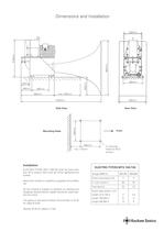
Dimensions and Installation 800mm 570mm 260mm 160mm 290mm 280mm 130mm 265mm max. 250mm 480mm 1320mm 450mm Mounting Holes Rear View 290mm Side View Front 265mm 4 mounting holes for M12 screws min. 170mm Installation ELECTRO–TYFON MTX 150/130 shall be fixed with four M12 screws that must be firmly tightened and locked. Mount the whistle on a platform supplied with a safety rail. As the whistle is subject to vibration on starting and stopping, flexible electric cables should be used nearest the motor. The gland on the electric Motor Terminal Box is M 25 for cable Ø 9-20. Optinal: M 32 for...
Open the catalog to page 2
Maintenance, Dismantling and Reassembling Maintenance The Crankshaft ELECTRO–TYFON is designed to give long reliable service without routine maintenance, but a periodic inspection always gives early warning of any faults that may develop. Unscrew the four M10 nuts (M) inside the crankcase and remove the mounting flange. Unscrew the M8 screw (Q) in the crankshaft bearing cover at the motor side of the crankcase. Install a long M8 screw in the thread and pull out the cover. Remove the spacer O-ring and circlip (F2) at the end of the crankshaft and press out the crankshaft from the motor side...
Open the catalog to page 3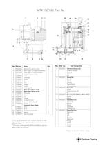
MTX 150/130: Part No. 3 5 2 1 26 25 24 23 21 20 4 19 22 18 29 27 6 11 12 7 8 Item 1 2* 2 3 4 5 6 7 8 11 12 15 16 16 17 18 19 20 21 22 23 24 Bearing (2 in set) for motor Motor type R 112 MBF/2-R 440/440V Motor type R 112 MBF/2-R 690V Connectiong box compl. Cover Crankcase Outlet Packing Horn Flange Cylinder Circlip SgA 28 Motor Gear Wheel, 50 Hz Motor Gear Wheel, 60 Hz Base plate Screw Cap Spacer O-ring 57,6 x 2,4 Bearing for Crankshaft Spacer Crankshaft Gear Wheel 50 Hz 60 Hz Bearing for Crankshaft Sealing Mounting flange 25 28 29 21768547 21768545 20880002 21768474 21768473 13 9 10 No....
Open the catalog to page 4All Kockum Sonics catalogs and brochures
-
 TYFON®
12 Pages
-
 ksm638en-06141
4 Pages
-
 KSM_335_AT150330
2 Pages
-
 LEVELMASTER® WIM
2 Pages
-
 LOADMASTER X5 ®
4 Pages
-
 LEVELMASTER general
12 Pages
-
 edirite.pdf
4 Pages
-
 L85.PDF
2 Pages
-
 KTV75-400.pdf
2 Pages
-
 KSM633-0523-LP75.pdf
2 Pages
-
 KSM276E-0519_ETD_100350.pdf
2 Pages
-
 Ksm250-0710-MKT75SERIES.pdf
2 Pages
-
 KSM_272_MKT_75-260.pdf
2 Pages
-
 KSM_335_AT150330.pdf
2 Pages
-
 KSM_335_AT150330_2.pdf
2 Pages
-
 KSM_334_AT150200.pdf
2 Pages
-
 KSM_520_MT150130-140.pdf
4 Pages
-
 KSM_333_AT_150-165.pdf
2 Pages
-
 KSM_332_AT_150-130.pdf
2 Pages
-
 KSM_602_MTX150120.pdf
4 Pages
-
 KSM_268_MKT150110.pdf
2 Pages
-
 KSM267E_MKT_15090.pdf
2 Pages


