
Catalog excerpts
This device complies with part 15 of the FCC Rules. Operation is subject to the following two conditions: (1) This device may not cause harmful interference,and (2) this device must accept any interference received, including interference that may cause undesired operation. This product complies with the essential requirements and other relevant provisions of Directive 2014/53/EU. The declaration of conformity may be consulted at https://hemispheregnss.com/About-Us/Quality-Commitment. Copyright Notice Copyright Hemisphere GNSS, Inc. (2017). All rights reserved. No part of this manual may be...
Open the catalog to page 2
A222 User Guide Chapter 1 - Introduction Page 1 of 20
Open the catalog to page 5
Introduction Overview Hemisphere GNSS’ all new scalable A222 was designed to excel in challenging environments, and is ideal for use with various applications, including precision agriculture, machine control, construction, mining, and marine. The A222 is a multi-GNSS RTK, high accuracy GNSS receiver that allows you to work quickly and accurately. Built on Hemisphere GNSS’ Eclipse™ platform, A222 boasts the latest GNSS patented technology and offers quick startup and reacquisition times. The A222 can be updated by adding L1/L2 GLONASS activations and subscriptions for Athena RTK and/or...
Open the catalog to page 6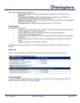
Atlas L-Band benefits include the following: • Positioning accuracy. Competitive positioning accuracies down to 4 cm RMS in certain applications • Positioning sustainability. Cutting edge position quality maintenance in the absence of correction signals, using Hemisphere’s patented technology • Scalable service levels. Capable of providing virtually any accuracy, precision and repeatability level in the 4 to 100 cm range • Convergence time. Industry-leading convergence times of 10-40 minutes Key Features Key features of A222 include: • Centimeter-level accuracy using Atlas* or Athena**...
Open the catalog to page 7
Chapter 2: Installation Display, Mounting, and Connectors LED Display Mounting A222 Powering A222 A222 User Guide Chapter 2 - Installation Page 4 of 20
Open the catalog to page 8
Installation Display, Mounting, and Connectors All connections and ports are located on the bottom of the unit, as shown in Figure 2-1. Table 2-1 provides additional information about each port/connection. Table 2-1: A222 Ports and Connections A222 User Guide Chapter 2 - Installation Page 5 of 20
Open the catalog to page 9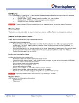
A222 uses a single LED (see Figure 2-1) that provides system information based on the color of the LED as follows: • Blinking Red - Power on • Blinking Amber - GNSS position available, including RTK float and Atlas • Blinking Green - RTK-fixed or Atlas-converged position available • Blinking any color - Receiver operational If at any time the LED turns to a solid color for an extended period, the receiver has malfunctioned. This section provides information on where to mount your antenna and the different mounting options available. Selecting the Proper Antenna Location Proper antenna...
Open the catalog to page 10
Surface Mount You can surface-mount A222 with four machine screws (no. 8-32).
Open the catalog to page 11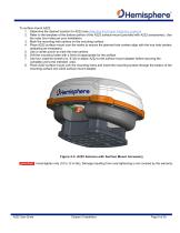
To surface-mount A222: 1. Determine the desired location for A222 (see Selecting the Proper Antenna Location). 2. Refer to the template of the bottom portion of the A222 surface-mount (provided with A222 accessories). Use the outer four holes per your installation. 3. Mark the mounting hole centers on the mounting surface. 4. Place A222 surface mount over the marks to ensure the planned hole centers align with the true hole centers (adjusting as necessary). 5. Use a center punch to mark the hole centers. 6. Drill the mounting holes with a 5mm bit appropriate for the surface. 7. Use four...
Open the catalog to page 12
Pole Mount The center thread on the bottom of A222 is 1-14 UNS. The mounting assembly included with A222 includes a 5/8-11 UNC adapter. Simply thread the riser/pole into the antenna until snug. Figure 2-4: Pole Mount Hand-tighten only (screws 10-12 in-lbs; pole 35-40 in-lbs.) . Damage resulting from over-tightening is not covered by the warranty.
Open the catalog to page 13
Powering A222 Power Considerations A222 accepts an input voltage of 8-32 VDC. For best performance use a clean and continuous power supply. When applying 12 VDC, A222 will draw approximately 3.2W. Connecting to a Power Source A222 uses a single cable for power and data input/output. Note: A power/data cable is not supplied with A222, but is available as an accessory item. See Table 1-1 for a list of accessory items. Note: The following information refers to using the accessory item cables available from Hemisphere GNSS. The antenna end of the cable is terminated with an...
Open the catalog to page 14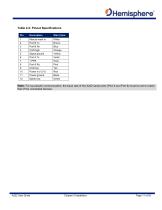
Table 2-2: Pinout Specifications A222 User Guide Chapter 2-Installation Page 11 of 20
Open the catalog to page 15
Chapter 3: Using A222 GNSS Operation Differential Operation Default Parameters Configuring the A222 A222 User Guide Chapter 3 - Using A222 Page 12 of 20
Open the catalog to page 16
Using A222 For your convenience, both the GNSS and differential correction of the A222 are preconfigured. The receiver will work out-of-the-box, and for most applications, little user setup is necessary. When powered for the first time, the A222 will perform a “cold start,” which involves acquiring the available GNSS satellites in view and the SBAS differential service. GNSS Operation The GNSS receiver is always operating, regardless of the DGNSS mode of operation. The following sections describe the general operation of the A222’s internal GNSS receiver. Automatic Tracking The A222’s...
Open the catalog to page 17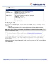
Configuring the A222 You can configure the A222 through the serial port using Hemisphere GNSS commands. For example, you can select the: • Baud rate • NMEA 2000 data message to output on the dual serial ports and the update rate of each message Note: Use the $JSAVE command to save changes you make to the A222’s configuration for the changes to be present in subsequent power cycles. For information on Hemisphere GNSS commands refer to the Hemisphere GNSS Technical Reference. Auto-Seed Auto-Seed allows the end user to shut down their device in a static position for any extended period of...
Open the catalog to page 18All Hemisphere GPS catalogs and brochures
-
 IronOne
1 Pages
-
 C321+ GNSS Smart Antenna
2 Pages
-
 Vector™ VR1000 GNSS Receiver
2 Pages
-
 A45™ ANTENNA
1 Pages
-
 A43™ ANTENNA
1 Pages
-
 HemisphereGNSS_A42_A52
1 Pages
-
 POCKETMAX4
43 Pages
-
 IRONVIEW CW400 DATA COLLECTOR
55 Pages
-
 CRESCENT P102/P103 OEM BOARDS
50 Pages
-
 A325
A32533 Pages
-
 A101 Smart Antenna
34 Pages
-
 S321+ GNSS SMART ANTENNA
2 Pages
-
 VECTOR™ V500 SMART ANTENNA
2 Pages
-
 VECTOR™ V1000 GNSS RECEIVER
2 Pages
-
 A325™ GNSS Smart Antenna
2 Pages
-
 S321
S3212 Pages
-
 HemisphereGNSS AtlasLink
2 Pages
-
 HemisphereGNSS XF3
2 Pages
-
 HemisphereGNSS V320
2 Pages
-
 Atlas Brochure
6 Pages
-
 S320? GNSS SURVEY RECEIVER
2 Pages
-
 A42? ANTENNA
1 Pages
-
 A21? ANTENNA
1 Pages
-
 CRESCENT VECTOR H200? BOARD
2 Pages
-
 R330? GNSS RECEIVER
2 Pages
-
 Marine_Brochure
2 Pages
-
 GNSS OEM Modules Brochure
2 Pages


Archived catalogs
-
 S320 Product Brochure
6 Pages

